1/4 gate length
1/4 gate length minus 14 inches
at least 9 inches
24 inches
28 inches
6 inches
(check local and
national codes)
QuickStart for single gate applications
This QuickStart is intended to highlight a single right-hand gate application. Each application is unique and it is the responsibility of the purchaser, installer and end user to ensure that
the total gate system is installed and operated properly. Refer to the installation manual for complete information regarding installation, testing, and programming.
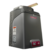
MODEL CSW24V
™
& CSW24VH
™
1 Install the concrete pad and conduit.
2 Attach the operator to the concrete pad.
3 Position the operator arm onto the output shaft so that the pin slides
into the slot.
2
4
6
7
3
1
5
4 Concrete Anchors
1/2" x 3 1/2"
INSTALLATION
8
9
4 Position the gate bracket on the gate (1/4 the length of the gate
from the gate hinge center). Ensure the arm is level.
5 Weld the gate bracket and long arm section in this position.
6 Weld the short arm section.
7 Secure the operator arm to the output shaft.
8 Tighten the handle.
9 Remove the pin from the vent plug on both the top and bottom
gear boxes.
INSTALL THE COVER
1 Remove the operator arm from the output shaft by
releasing the handle.
2 Align the tabs on the rear cover with the slots on the chassis
and place the cover over the operator.
3 Secure both sides of the rear cover to the chassis with two
5/16-18 hex bolts and washers.
4 Reattach the operator arm to the output shaft (making sure
the pin fits into the slot) and secure by pushing the handle
down.
5 Place the operator arm cover over the operator arm and
secure.
6 Align the front cover with the back cover, making sure the
grooves line up.
7 Secure the front cover to the chassis with two 5/16-18 hex
bolts and washers.
8 Secure the front cover to the rear cover using the 5/16-18
screw.
Tabs on Rear Cover
Slots on Chassis
Groove on Front Cover
5/16-18
Hex Bolts
and Washers
5/16-18
Screw