Do you have a question about the Chamberlain LiftMaster Professional Security+ 3265-267 and is the answer not in the manual?
Lists the necessary tools for assembly and installation.
Crucial safety and procedural guidelines before starting installation.
Critical safety rules for operating the garage door opener.
Basic instructions for activating the opener and door movement.
Details the functions of the main wall-mounted control panel.
How to control the opener's light using the control panel.
Disables remote control operation for security.
Programming remote buttons for light control and operation.
Explains how weather affects settings and need for re-adjustments.
Outlines monthly, semi-annual, and annual maintenance tasks.
Instructions for replacing the battery in the remote control.
Addresses problems like door not closing, remotes not working, or door reversing.
Guides on pairing remotes with the opener.
Resets all previously programmed remote codes.
Information on using additional buttons on 3-button remotes.
Procedure for changing a known Keyless Entry PIN.
Creates temporary access codes for visitors or service personnel.
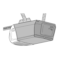
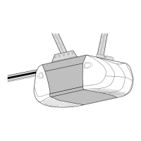
Identifies parts specific to the opener's rail system.
Lists components required for installing the opener and its accessories.
| Type | Chain Drive |
|---|---|
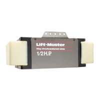
| Horsepower | 1/2 HP |
| Voltage | 120V |
| Frequency | 60 Hz |
| Security Features | Security+ 2.0 |
| Remote Control | Yes |
| Max Lift Height | 7 feet |
| Drive Type | Chain Drive |
| Battery Backup | No |
| Wi-Fi Capable | No |
| Operating Frequency | 315 MHz |
| Lighting | 100-watt (max) light |
| Warranty | Lifetime motor warranty |
| Motor Type | AC Motor |