12
Installation (continued)
CAUTION
• To AVOID damaging gas, power
or other underground utility
lines, contact underground utility
locating companies BEFORE
digging more than 18 inches (46
cm) deep. In the US, call 811.
• Permanent wiring is to be employed as required by local codes. It is
important to ensure proper grounding of the unit.
• To avoid creating an entrapment zone, do not install this vehicular
barrier arm gate operator in a manner in which the arm moves within 16
in. (406mm) of a rigid object in a location up to 6ft. (1.8m) above grade.
Examples include walls, ceilings, posts, pillars, columns, or guard shacks.
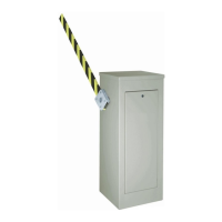
Operator and Arm Installation Options
NOTE: The Barrier Arm is not included and must be purchased separately. See “Accessories” on page 57.
The barrier arm gate operator may be installed with right-hand or left-hand operation. The barrier arm may be installed
with or without the Arm Breakaway setup.
CAUTION: If the Arm Breakaway setup is not used, damage to the operator may occur.
NOTE: The barrier must be fully open (arm/bracket in the vertical position) before modifying the counterbalance spring
assembly.
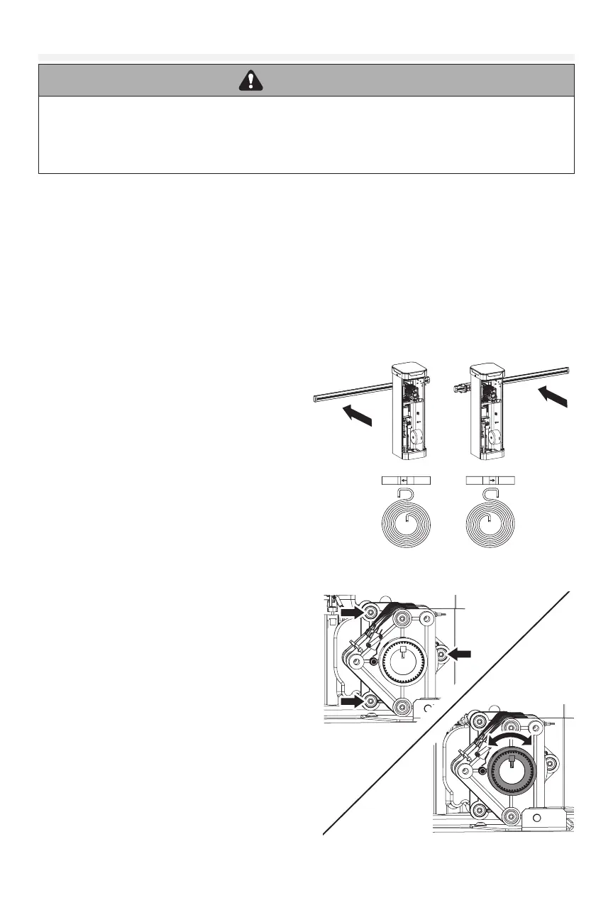
1. Determine whether the operator installation shall use Right-Hand Operation or Left-Hand Operation.
HANDING OPTIONS
The barrier arm gate operator may be installed with
right-hand or left-hand operation.
See the image to determine the handing in relation to
the operator when facing the opening of the cabinet.
COUNTERBALANCE SPRINGS DIRECTION
The arrow of each installed spring must point in
the direction of the arm in the closed position for
left- or right-handing. The counterbalance spring
assembly comes from the factory in the right-handed
conguration.
Reinstall all springs in the proper direction when the
handing is changed. For instructions, see “Reverse
the Spring Handing” on page 16.
WARNING: FOLLOW THE STEPS OUTLINED IN “REMOVING SPRING TENSION” TO ENSURE THAT ALL TENSION IS
RELEASED FROM SPRINGS PRIOR TO REMOVING BOLTS, OR THE END PLATE.
REMOVING SPRING TENSION
ATTENTION: The steps below must be used to safely
remove springs from a PBG, CBG, or IBG operator. They
allow the spring assembly to disengage from the gearbox
while it is still mounted in place.
1. Locate the three bolts that attach the spring assembly
to the gearbox. Using a socket wrench and extension
to avoid accidental contact with the loaded springs
inside the cabinet enclosure, loosen each screw by 3
full rotations only. Do NOT fully remove these bolts yet.
2. Use a athead screwdriver or pry bar around the
edges of the spring assembly to disengage it from the
gearbox, avoiding contact with the springs and center
hub. Do not use hands or body to release tension.
3. Verify the springs are loose before removing the three
bolts completely. The shaft of the spring assembly
should be able to move a few degrees by hand if the
springs are disengaged.
NOTE: The Handing of the Barrier Arm may be changed from right-hand to left-hand operation, and vice versa.
Left Handing
Right Handing