Do you have a question about the Champion L Series and is the answer not in the manual?
Details the benefits of genuine parts and distributor support services for reliability and performance.
Provides contact information and methods to locate authorized Champion distributors.
Guidelines for specifying compressor model, serial number, and required parts for ordering.
Explains the use of warning, prohibition, and mandatory label information in the manual.
Defines DANGER level hazards and lists associated safety symbols.
Defines WARNING level hazards and lists associated safety symbols.
Defines CAUTION level hazards and lists associated safety symbols.
Lists required and prohibited actions for safe compressor operation.
Lists critical safety measures to avoid death or serious injury.
Lists safety measures to avoid equipment damage.
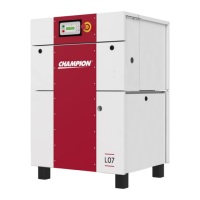
Describes the rotary screw compressor mechanism and its components.
Explains how air is compressed by the meshing rotors.
Details the path of air through the compressor system.
Explains the role of oil in lubrication, cooling, and sealing.
Covers initial checks and general advice for unit installation.
Provides instructions and precautions for safely lifting the compressor unit.
Specifies environmental and spatial requirements for unit placement.
Details ventilation requirements for air-cooled units.
Describes foundation requirements and mounting considerations.
Explains how to drain the oil sump and oil cooler.
Discusses maintenance access and proper enclosure operation.
Covers wiring according to electrical codes and standards.
Provides data for sizing electrical power wires.
Details equipment grounding according to the National Electrical Code.
Information on motor lubrication and sealed bearings.
Advises on installing the unit inside a heated shelter for cold climates.
Specifies requirements for an auxiliary air receiver if used.
Information on the optional moisture separator and trap.
Details control piping, inlet, and discharge service line connections.
Steps to check and service before operating a new unit.
Guidance on inspecting the air filter and inlet line.
Instructions for checking piping and electrical connections.
Notes on grounding and operating with a compressed air dryer.
Instructions for unpacking and checking the v-belt system.
Procedures for checking and ensuring correct motor rotation.
Details the controller layout, buttons, and display functions.
Instructions for adjusting pressure settings on the controller.
Guidance on choosing the automatic operation mode.
Step-by-step guide for starting the compressor unit.
Steps for stopping compressor operation.
Lists daily checks to perform on the unit.
Overview of the compressor package's pre-wired controls and starter.
Details the functions and features of the GD Pilot controller.
Explains the purpose and location of the emergency stop button.
Describes the control transformer and fuse block functions.
Information on terminal strips and main starter types for fixed/variable speed models.
Guidance on field conversion of the multi-voltage electrical system.
Captures solid impurities and attenuates inlet noise.
Controls atmospheric air intake during load/unload phases.
Drives the compressor and ventilation fan via a belt drive.
Covers oil sump, air/oil separator, filler cap, drain, level indicator, and filter.
Details the oil cooler and the pressure relief valve function.
Maintains minimum pressure and prevents backflow.
Describes the air cooler and scavenge line orifice.
Describes solenoid valve and sump pressure sensors.
Details sump temperature sensor, receiver, and refrigerated dryer.
Covers dryer bypass, drain isolation, and condensate drain valves.
Explains pressure relief valve and pressure gauge on the receiver.
Overview of the oil system components.
Details how oil is circulated for cooling and lubrication.
Information on Champion RotorLub lubricants.
Specifies oil type and how to check the oil level.
Information on lubricant compatibility and Safety Data Sheets.
Step-by-step guide for changing the compressor lubricant.
Procedure for adding oil when the level is low.
Recommended intervals for changing compressor lubricant based on temperature.
Detailed steps for draining and refilling the oil system.
Discusses preventing and identifying water contamination in the oil.
Explains the thermostatic mixing valve's role in regulating oil temperature.
Describes the oil sump's function in separation and storage.
Details the separator's role and factors affecting its performance.
Explains how to monitor pressure drop across the separator.
Procedure for inspecting and replacing filter and separator elements.
Explains how heat is rejected from oil to air.
Describes the air-cooling system and fan setup.
Instructions for cleaning heat exchanger exterior fins.
Details the single-stage cellulose media air filter.
Procedure for inspecting and replacing the air filter element.
Instructions for cleaning and replacing the pre-filter media.
Explains power transmission via v-belts, sheaves, and bushings.
Steps to prepare the belt system after unpacking.
How to check and ensure proper alignment of sheaves.
Step-by-step guide for replacing the v-belts.
Procedure for replacing sheaves and bushings.
Details the inlet valve assembly and its function.
Procedure for inspecting and potentially repairing the inlet valve body.
Explains the relief valve's purpose and how to test it.
Covers MPV inspection, replacement, and setting adjustment.
Procedure for inspecting the TMV for proper temperature regulation.
Guidance on input shaft seal leaks and repairs.
Steps for inspecting and cleaning the electrical box cooling hardware.
Procedures for removing and replacing VFD cooling fans.
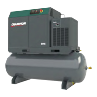
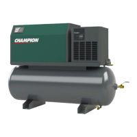
Overview of tank-mounted compressors with optional dryers.
Key considerations for installation, discharge piping, and dryer operation.
Details electrical power connections and optional general purpose filters.
Lists maintenance tasks and their recommended intervals.
Details checks required at 8, 125, 2000, and 4000-hour intervals.
Outlines maintenance tasks to be performed yearly.
Lists causes and remedies for the compressor not starting.
Addresses issues with short run times, cycling, and slow starts.
Covers problems with loading, unloading, and pressure range.
Causes and remedies for the compressor failing to reach load pressure.
Identifies causes and solutions for high discharge air temperatures.
Explains causes and remedies for excessive oil consumption.
Addresses causes and remedies for oil carryover.
Covers issues with water in the delivered air.
Details operating voltage ranges and their impact on the compressor.
Describes symptoms related to high or low supply voltage.
| Voltage | 230 |
|---|---|
| Stages | 2 |
| Noise Level | 78 |
| Tank Capacity | 80 gallons |
| Tank Size | 80 gallons |