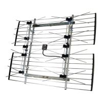
3000hrn
transmission
line
'r-r.1=,...,.,I.)
Ground
wire
from
mast
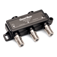
ANTENNA DISCHARGE UNIT
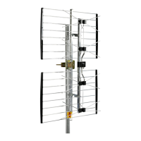
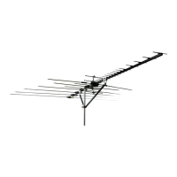
HOW TO INSTALL YOUR ANTENNA
1.
Assemble your new antenna on the ground in accordance with separate assembly instructions
supplied with it.
2. On the ground, clamp antenna to mast. pull enough transmission line to connect to antenna.
3.
Install selected mounting bracket.
4. If you are going to use
guy
wire installation instead
of
a mounting bracket:
Install-guy anchor bolts
• Estimate length
of
guy
wire and cut
• Attach to mast using
guy
ring
5.
Mount the extra included
~Warning
Laber
supplied in the hardware bag on the antenna mast at
eye level after installation as been completed.
LIGHTNING PROTECTION
To
protect your house and your
TV
(FM, CB, etc.) installation, the mast
of
your antenna system
must
be properly grounded. Drive a 4 to 8 foot ground rod as close as possible
to
the antenna supporting
structure or antenna base. Then connect a
#8
(or larger) copper or aluminum wire between the base
of the antenna and the ground rod. Also, an antenna discharge unit (sometimes- referred to as a
lightning arrester) should
be
connected to the antenna lead-in at the place where it enters the
home.
(Follow the instructions provided with the static discharge unit.)
ANTENNA REMOVAL
Removal
of
the antenna should be exactly the reverse
of
the installation instructions. Please, for
your own safety, follow the instructions for installing the antenna starting with the last step first.
This is the safest method.
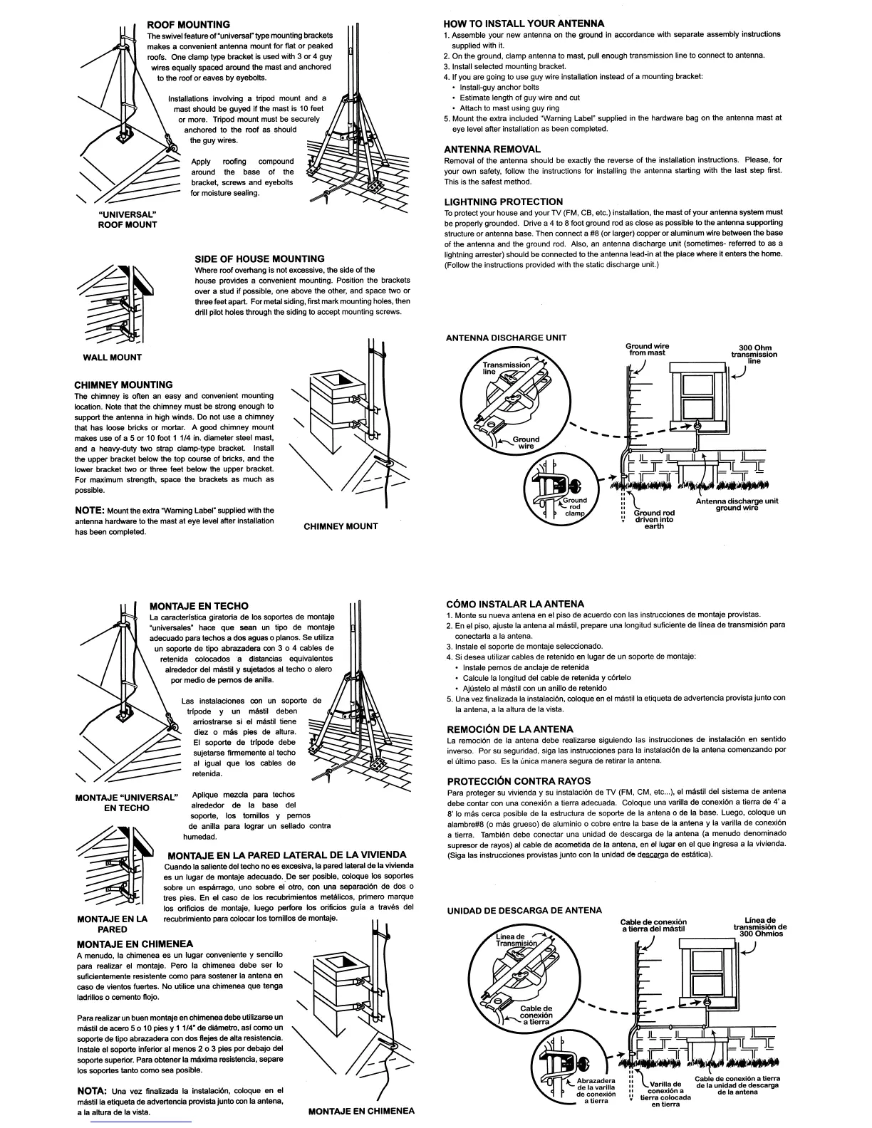
CHIMNEY MOUNT
SIDE OF HOUSE MOUNTING
Where
roof
overhang is not excessive.
the
side
of
the
house provides a convenient mounting. Positton the brackets
over a stud
if
possible. one above the other, and space two
or
three feet apart. For metal siding, first
mark
mounting holes, then
drill pilot holes through the siding to accept mounting screws.
Apply roofing compound
around the base of the
bracket, screws and eyebolts
for moisture sealing.
Installations involving a tripod mount and a
mast should be guyed
if
the mast is 10 feet
or
more. Tripod
mount
must be securely
anchored to the roof
as
should
the
guy
wires.
NOTE: Mountthe extra "Warning Label" supplied with the
antenna hardware to
the
mast at
eye
level after installation
has been completed.
CHIMNEY MOUNTING
The chimney is often an easy and convenient mounting
location. Note that the chimney
must
be
strong enough
to
support the antenna in htgh winds.
Do
not use a chimney
that has
kx>se bricks
or
mortar. A
good
chimney
mount
makes use
of
a 5
or
10 foot 1 1/4 in. diameter steel mast.
and a heavy-<luty
two
strap
damp-type
bracket. Install
the upper bracket below the
top
course of bricks, and the
lower bracket two
or
three feet below the upper bracket.
For maximum strength, space the brackets as much as
possible.
"UNIVERSAL"
ROOF MOUNT
ROOF MOUNTING
The
swivel feature
of
·universal-type mounting brackets
makes a convenient antenna mount for flat
or
peaked
roofs.
One
clamp type bracket is used
with
3
or
4 guy
wires equally spaced around
the mast and anchored
to
the
roof
or
eaves
by
eyebolts.
WALL
MOUNT
Cable
de
conexi6n
Linea
de
a
tierra
del
mastil
transmisi6n
de
r------,
3000hmlo.
,,",",==::I'""'T1I..J
REMOCI6N DE
LA
ANTENA
La remoci6n de la antena debe realizarse siguiendo las instrucciones de instaraci6n en sentido
inverse. Por su seguridad, siga las instrucciones para la instalaci6n de la antena comenzando par
el ultimo paso.
Es
la (mica manera segura de retirar la antena.
C6MO
INSTALAR
LAANTENA
1. Monte su nueva antena en el piso de acuerdo con las instrucciones de montaje provistas.
2. En el piso, ajuste la antena al mllstil, prepare una longitud suficiente de linea
de
transmisi6n para
conectarla a la antena.
3.
Instale el soporte de montaje seleccionado.
4.
8i
desea utilizar cables de retenido en lugar de un soporte de montaje:
Instale parnos de anclaje de retenida
• Calcule la longitud del cable de retenida y c6rtelo
• Ajustelo al mllstil con un anillo de retenido
5.
Una vez finalizada la instalaci6n, coloque en el
mllstilla
etiQueta de advertencia provista junto con
la antena, a la altura de la vista.
PROTECCI6N CONTRA RAYOS
Para proteger su vivienda y su instalaci6n de
TV
(FM, CM, etc
...
),
el mllstil del sistema de antena
debe contar con una conexi6n a tierra adecuada. Coloque una varilla
de
conexi6n a tierra de
4'
a
8'
10
mas cerca posible de la estructura de soporte de la antena 0 de la base. Luego, coloque
un
alambre#8
(0
mas grueso) de aluminio 0 cobre entre la base de la antena y la varilla de conexi6n
a tierra. Tambien debe conectar una unidad de descarga de la antena (a menudo denominado
supresor de rayos) al cable de acometida de la antena, en
e/lugar
en el
que
ingresa a la vivienda.
(8iga
las instrucciones provistas junto con la unidad de
d~rga
de
eslatica).
UNlOAD DE DESCARGA DE ANTENA
MONTAJE EN CHIMENEA
Aplique
mazda
para tachos
alrededor de la base del
soporte, los tomillos y pernos
de anilla para I09rar
un
sellado contra
humedad.
Las instalaciones
con
un
soporte
trfpode y
un
mllstil deben
arriostrarse
si
el mllstil liene
diez
0
mlIs
pies de altura.
EI
soporte
de
trfpode
debe
sujetarse firmemente
al
tacho
al igual
que
~
cables de
retenida.
MONTAJE EN
LA
PARED
LATERAL
DE
LA
VIVIENDA
Cuando la saliente del techo
no
as excesiva,
ta
pared lateral
de
Ia
vMenda
as
un
lugar
de
montaje adecuado..De ser posibfe, coIoque los soportes
sobre un espllrrago,
uno
sobre
eI
otro,
con
una separaci6n de dos 0
tres pies.
En
el caso de los recubrimientos metlllicos, primero marque
los orificios de montaje, luego
perfore los orificios gufa a traves del
recubrimiento para colocar los tornillos de montaje.
MONTAJE
EN
TECHO
La caracterfstica giratoria
de
los soportes de montaje
·universales- hace
que
sean
un
tipo de montaje
adecuado para techos
a
dos
aguas 0 p(anos.
sa
utiliza
un
soporte
de
tipo abrazadera
con
3 0 4 cables de
retenida colocados 'a distancias equivalentes
alrededor del mllstil y sUjetados al tacho
0 alero
por medio de
pernos
de
anUla.
Para realizarun buen montajeen chimenea debeutilizarse
un
mbtil
de aoore 5 0
10
pies y 1 1/4"
de
diamelro,
asi
como
un
soporte de tipo abrazadera con
dos
f1ejes
de alta resistencia.
Instale el soporte inferior al menos 2 0 3 pies por debajo det
soporte superior. Para obtener la mlIxlma resistencia, separe
los soportes tanto
como
sea posible.
MONTAJE EN
LA
PARED
MONTAJE
EN
CHIMENEA
A menudo, la chimenea
es
un
lugar conveniente y sancillo
para realizar el montaje. Pero la chimenea debe
ser
10
suficientemente resistente
como
para sostener
Ia
antena en
caso de vientos fuertes.
No
utilice una chimenea
que
tenga
ladrillos 0 oomento
fIojo.
MONTAJE "UNIVERSAL"
ENTECHO
NOTA: Una vez finalizada
Ia
in.tataci6n, coloque
en
el
mastilla
etiqueta
de
advertencia provistajunto con
Ia
antena,
a la altura de
Ia vista.
 Loading...