GB
44
CN
GR
FR
SP
PT
Instructions pertaining to the installer
General information
Warning: When the selector switch
(1)
is set on Wintertime operation
( )
it may be
necessary to wait some minutes at each intervention of the central heating temperature
adjusting control
(5).
To relight the main burner immediately place the selector switch
(1)
on
(0)
and then again on
( ).
No waiting is needed when the boiler is in the DHW mode
on models with this option.
The following remarks and instructions are addressed to Service Engineers to help them
carry out a faultless installation. Instructions regarding lighting and operation of the boiler
are contained in the ‘Instructions pertaining to the user’ section.
Note that installation, maintenance and operation of the domestic gas appliances must be
performed exclusively by qualied personnel in compliance with current standards.
Please note the following:
*
This boiler can be connected to any type of double- or single feeding pipe convector
plates, radiators, thermoconvectors. Design the system sections as usual though
taking into account the available output / pump head performances, as shown on
page 50.
* Do not leave any packaging components (plastic bags, polystyrene, etc.) within
children’s reach as they are a potential source of danger.
*
Initial lighting of the boiler must be effected by a Qualied Service Engineer.
Failure to observe the above will render the guarantee null and void.
Instructions prior to installation
This boiler is designed to heat water at a lower than boiling temperature at atmospheric
pressure. The boiler must be connected to a central heating system and, on models
withis option, to a domestic hot water supply system in compliance with its performances
and output power.
Before connecting the boiler have the following operations effected:
a)
careful checking that the boiler is t for operation with the type of gas available. For
more details see the notice on the packaging and the label on the appliance itself.
b) careful checking that the ue terminal draft is appropriate; that the terminal is not
obstructed and that no other appliance exhaust gases are expelled through the same
ue duct, unless the ue is especially designed to collect the exhaust gase coming
from more than one appliance, in conformity with the laws and regulations in force
c)
careful checking that, in case the ue has been connected to pre-existing ue ducts,
thorough cleaning has been carried out in that residual combustion products may
come off during operation of the boiler and obstruct the ue duct.
To ensure correct operation of the appliance and avoid invalidating the guarantee, observe
the following precautions
1.
Hot water circuit
if the water hardness is greater than 20 °F (1 °F = 10 mg calcium carbonate per litre of
water) install a polyphosphate or comparable treatment system responding to current
regulations
2.
Heating circuit
2.1. new system
Before proceeding with installation of the boiler, the system must be cleaned
and ushed out thoroughly to eliminate residual thread-cutting swarf, solder and
solvents if any, using suitable proprietary products
2.2.
existing system:
Before proceeding with installation of the boiler, the system must be cleaned
and ushed out to remove sludge and contaminants, using suitable proprietary
products
To avoid damaging metal, plastic and rubber parts, use only neutral cleaners, i.e. non-
acid and non-alkaline (e.g. SENTINEL X400 and X100), proceeding strictly in accordance
with the maker’s directions
Remember that the presence of foreign matter in the heating system can adversely affect
the operation of the boiler (e.g. overheating and noisy operation of the heat exchanger)
The template to fix the boiler on the wall
Decide upon the boiler location, then tape the template on the wall.
Connect the pipework to the gas and water inlets prearranged on the template lower
bar.
We suggest you t two G3/4 stop cocks (available on demand) on the central heating
system ow and return pipework; the cocks will allow to carry out important operations
on the system without draining it completely.
If you are either installing the boiler on a pre-existent system or substituting it, we
suggest you also t settling tanks on the system return pipework and under the boiler
to collect the deposits and scaling which may remain and be circulated in the system
after the purge.
When the boiler is xed on the template connect the ue and air ducts (ttings supplied
by the manufacturer) according to the instructions given in the following sections.
When installing the 2.24 CF model boiler with natural draught, make the connection to the
ue using a metal pipe which will provide resistance over time to the normal mechanical
stresses, heat and the effects of the combustion products and any condensation they
form.
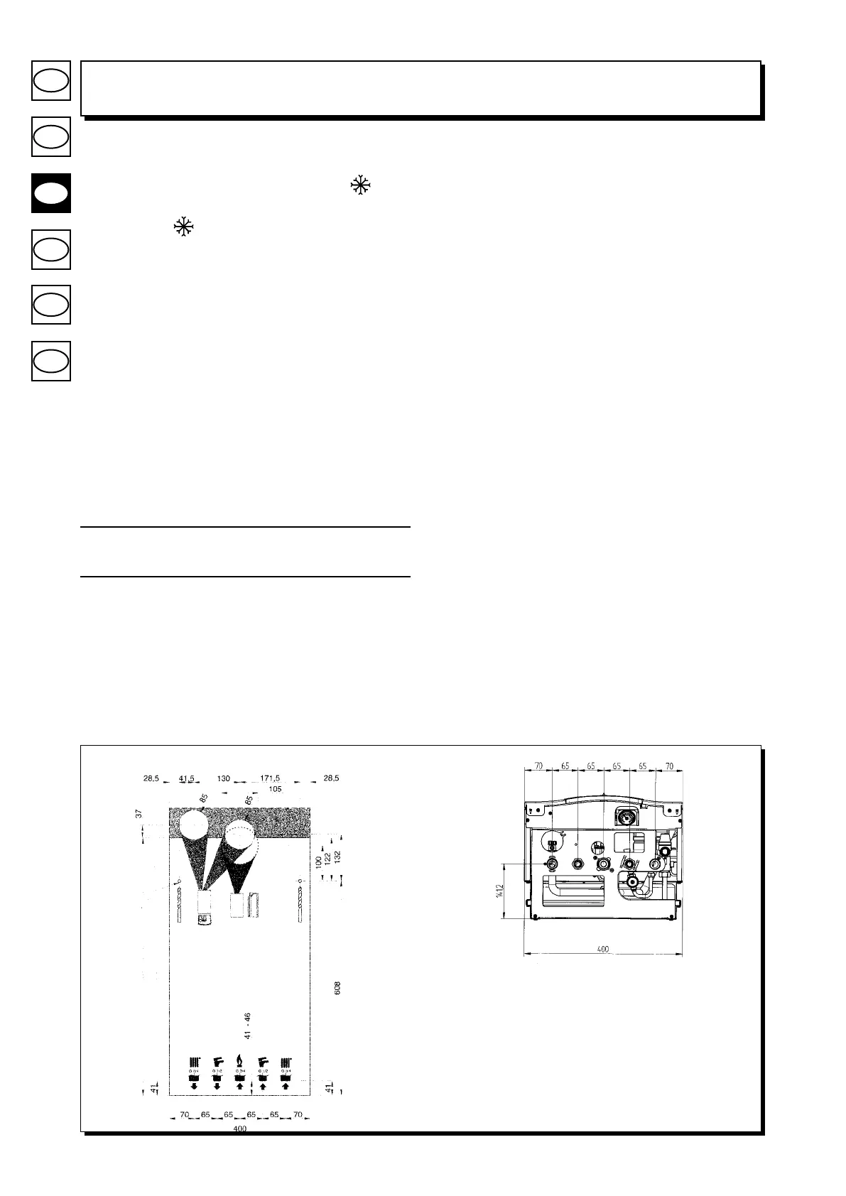
Figure 5
MR: G3/4 heating flow
US: G1/2 domestic hot water outlet
GAS: G3/4 gas inlet to the boiler
ES: G1/2 cold water inlet
RR: G3/4 heating return
0303_2808
0309_1101
BOILER CONNECTION POINTS
BOILER HEIGHT 730