49
GB
CN
GR
FR
SP
PT
020130_0800
Figure 9
CO2%
(L1+L2)
MAX CONTROL POSITION
G.20 G.30 G.31
0÷4 1
4÷18 2 6,7
7,3 7,3
18÷30 3
indice
opening
Connecting the mains supply
Electrical safety of the appliance is only guaranteed by correct grounding, in compliance
with the applicable laws and regulations.
Connect the boiler to a 220-230V monophase + ground power supply by means of the
three-pin cable supplied with it and make sure you connect polarities correctly.
Use
a double-pole switch with a contact separation of at least 3mm in both po-
les.
In case you replace the power supply cable t a HAR H05 VV-F’ 3x0.75mm
2
cable with
an 8mm diameter max.
…access to the power supply terminal block
• isolate the electrical supply to the boiler by the double-pole switch;
• unscrew the two screws securing the control board to the boiler;
• rotate the control board;
•
unscrew the lid and gain access to the wiring (Figure 10).
A 2A fast-blowing fuse is incorporated in the power supply terminal block (to check or
replace the fuse, pull out the black fuse carrier).
(L) = Live brown
(N) = Neutral blue
(
) = Ground yellow/green
(1) (2) = room thermostat terminal
Figure 10
020130_0900
terminal board
Figure 11
9402250715
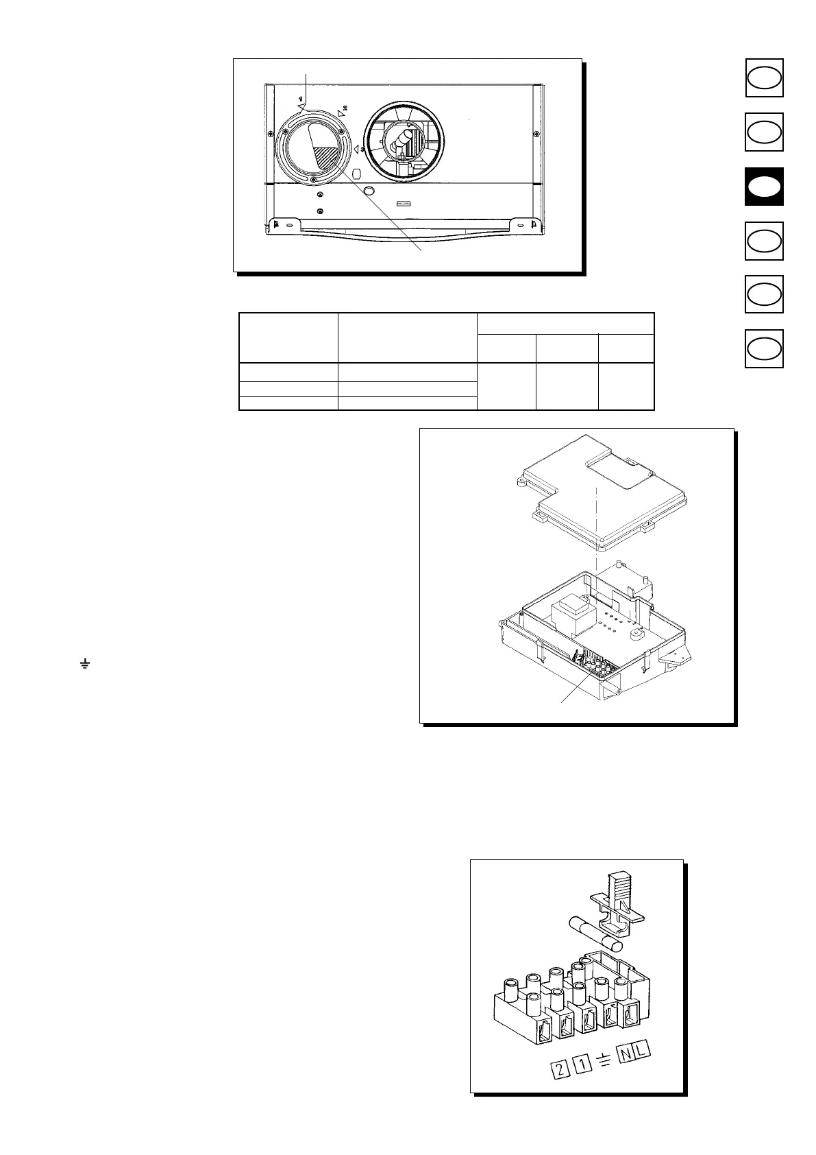
Fitting a room thermostat
• gain access to the power supply terminal block (Figure 11) as described in the previous
section;
• remove the jumper placed on terminals (1) and (2);
• insert the duplex cable through the core hitch and connect it to the two terminals.
Connecting a programming clock
* connect the programming clock motor to the main PCB CN1 connector (terminals
1 and 2);
* connect the programming clock switch to the CN1 connector terminals (3 and 4) and
remove the jumper.
In case you are tting a battery-operated programming clock do not connect the CN1
connector terminals (1 and 2).