GB
48
CN
GR
FR
SP
PT
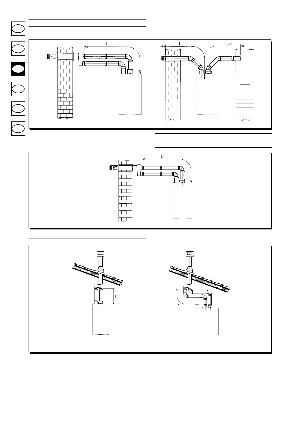
(L1 + L2) max = 30 m
L max = 10 m
NB: For C52 types, terminals for combustion air suction and combustion product extrac-
tion must never be tted on opposite walls of the building.
L max = 10 m
L max = 12 m
Separated vertical flue terminals installation options
Important: if tting a single exhaust ue duct, ensure it is adequately insulated (e.g.: with
glass wool) wherever the duct passes through building walls.
For detailed instructions concerning the installation of ttings refer to the technical data
accompanying the ttings.
Split
flue air control adjustment
The adjustment of this control is required to optimise performance and combustion param-
eters. The air suction coupling can be rotated to adjust excess air according to the total
length of the ue and intake ducts for the combustion air.
Turn this control clockwise to increase excess combustion air and anticlockwise to
decrease it.
The maximum length of the suction duct must be 10 metres.
If the ue duct exceeds 6 m, the condensate collection kit (supplied as an accessory)
must be tted close to the boiler.
To improve optimisation a combustion product analyser can be used to measure the CO
2
contents of the ue at maximum heat output, gradually adjusting air to obtain the CO
2
reading in the table below, if the analysis shows a lower value.
To properly install this device, also refer to the technical data accompanying the tting.
Separated horizontal flue terminals installation options
IMPORTANT: Ensure a minimum downward slope of 1 cm toward the outside per each
metre of duct length.
In the event of installation of the condensate collection kit, the angle of the drain duct
must be directed towards the boiler.
0609_1102
0503_0911 / CG_1644
0503_2201 / CG_1643