Do you have a question about the Chattanooga Group Vectra Genisys and is the answer not in the manual?
Explains the main components and functions of the therapy systems, including power, boards, and interfaces.
Details specific modules like NiMH Battery, Laser, sEMG, and Operator Remote, outlining their functions and interfaces.
Defines safety symbols and lists critical operational safety instructions for user protection.
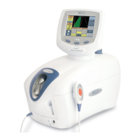
Identifies major components of the therapy system and its variations, referencing specific pages for details.
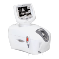
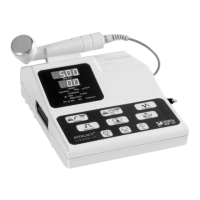
Details exterior components of the two-channel combination therapy systems.
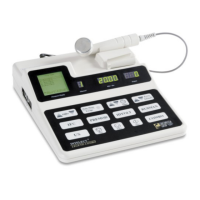
Identifies exterior components of two-channel electrotherapy systems.
Details exterior components of the channel 3/4 electrotherapy module.
Identifies exterior components of the NiMH battery module.
Details exterior components of the laser module.
Identifies exterior components of laser therapy system applicators.
Details exterior components of the dual channel sEMG module.
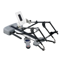
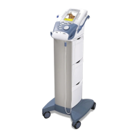
Identifies exterior components of the therapy system cart.
Details exterior components of the operator remote control.
Defines system symbols for hardware, software, and optional accessories.
Provides physical dimensions and power specifications for the therapy systems.
Details specifications for various electrotherapy waveforms like IFC, TENS, HVPC, VMS, Russian, Microcurrent.
Lists frequency, duty cycles, output power, and beam characteristics for ultrasound.
Explains safety and compliance markings found on the devices.
Provides power input and output specifications for the laser module.
Details wavelength, output power, and power density for single diode laser/LED applicators.
Lists specifications for 9, 13, and 19 diode cluster laser and LED applicators.
Provides specifications for 33 diode cluster laser and LED applicators.
Lists error codes, probable causes, and possible remedies for system malfunctions.
Covers visual checks, leakage tests, unit startup, and fan testing procedures.
Details the setup for testing stimulator outputs using an ESTI-2 fixture.
Describes testing procedures for the VMS waveform mode.
Outlines testing procedures for the Interferential mode.
Details testing procedures for the Premodulated mode.
Describes testing procedures for the Russian mode, including Patient Interrupt Switch.
Outlines testing procedures for the microcurrent mode (Note: not for Intelect Vet).
Details testing procedures for the HVPC mode.
Describes testing procedures for the microcurrent probe mode.
Covers equipment needed and procedures for general ultrasound testing.
Details how to test if the system correctly identifies the ultrasound applicator.
Describes how to test the output power of ultrasound applicators.
Outlines how to test the duty cycle performance of ultrasound applicators.
Details testing procedures for combined ultrasound and electrotherapy modes.
Describes tests for sEMG functionality and combined sEMG with stimulation.
Covers checks for damage and proper connections of the NiMH battery module.
Provides step-by-step instructions for installing and removing various modules.
Details the process for installing and removing the sEMG module.
Explains how to separate the top and bottom housing of the therapy system.
Details the procedure for removing and replacing the system's cooling fan.
Provides instructions for removing and replacing the control board assembly.
Details how to remove and replace the keymat assembly.
Explains the process for removing and replacing the connector board.
Details how to remove and replace the ultrasound board in combination systems.
Provides instructions for removing and replacing the stim board.
Details the procedure for removing and replacing power supply units.
Explains how to remove and replace the connector board on the 3/4 electrotherapy module.
Details the process for removing and replacing the stim board on the 3/4 electrotherapy module.
Describes how to mount and dismount the therapy system onto its cart.
Covers procedures for cleaning the therapy system and its lenses.
Outlines annual calibration requirements for ultrasound and laser applicators.
Defines requirements for field service and factory service procedures.
Lists tools and equipment needed for ultrasound applicator calibration.
Details the step-by-step process for calibrating ultrasound applicators.
Lists parts for the top-to-bottom assembly of the therapy system.
Details parts for the combination system base assembly.
Lists parts for the combination stim and ultrasound PC board assembly.
Details parts for the top housing assembly of the therapy system.
Lists parts for the control board assembly for Vectra Genisys and Intelect Vet.
Details parts for the Intelect Legend XT control board assembly.
Lists parts for the Channel 3/4 Electrotherapy Module assembly.
Provides circuit diagrams for the system's control board.
Offers circuit diagrams for the ultrasound PC board.
Presents circuit diagrams for the system's stim board across multiple sheets.
Provides circuit diagrams for the system's connector board.
Offers circuit diagrams for the 3/4 electrotherapy module's connector board.
Presents circuit diagrams for the system's power supply units.
Provides circuit diagrams for the laser module board.
Details the warranty terms, coverage, and claim procedures for the products.
| Brand | Chattanooga Group |
|---|---|
| Model | Vectra Genisys |
| Category | Medical Equipment |
| Language | English |