EasyManuals Logo
Home>Chenbro>Chassis>SR301 series

Chenbro SR301 series User Manual

Default Icon
20 pages
To Next Page IconTo Next Page
To Previous Page IconTo Previous Page
Page #17 background imageLoading...
Page #17 background image
4-port 12Gb/s SAS/ SATA Backplane - 80H10230101A0 User Manual
Table 8. HDD Status LED Color Code
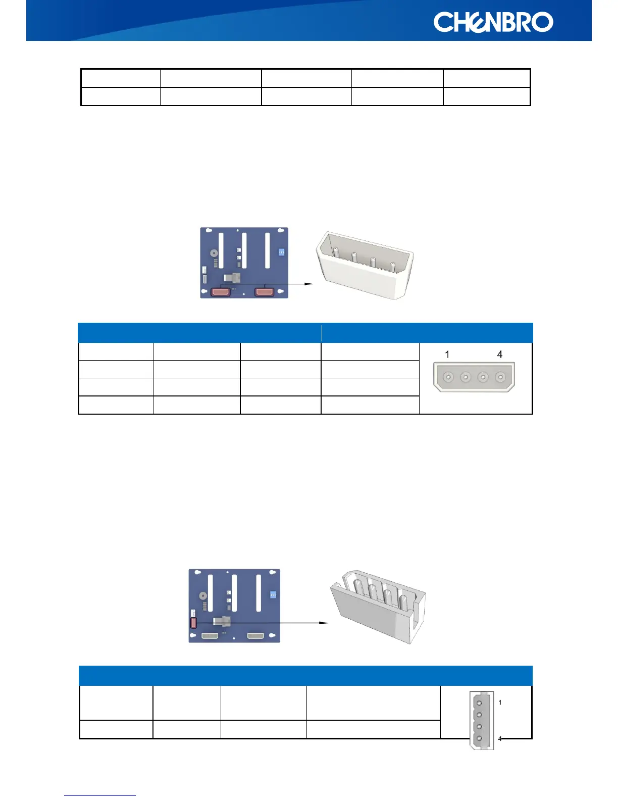
3.5 4-pin peripheral power connector (CN01and CN02)
These two connectors are used to power four 3.5” hard disks, connected to this backplane, and
each can ensure that all drives are supplied with stable power inputs. If the chassis fan is also
powered by fan header (JF01), this configuration is strongly recommended.
Pin Number
Pin Definition
Input/output
Description
Picture
1
12V
Input
Power +12V
2
GND
GND
Power GND
3
GND
GND
Power GND
4
5V
Input
Power +5V
Table 9. Pin assignment of Power connector
3.6 I2C Connector (JC01), IPMI Compliant
The motherboard can monitor HDD temperature and fan status through this connector. However,
the I2C connector on motherboard side is vendor dependent, so please contact our field
application engineers to fully utilize this feature.
Locate
On
Off
4Hz Blinking
SGPIO
Rebuild
On
Off
1Hz Blinking
SGPIO
PIN-Number
PIN-Define
Input/output
Description
Picture
1
SDA
I/O
I2C Data Signal
(Internal pull high +5V)
2
GND
GND
GND

Questions and Answers:

Question and Answer IconNeed help?

Do you have a question about the Chenbro SR301 series and is the answer not in the manual?

Chenbro SR301 series Specifications

General IconGeneral
BrandChenbro
ModelSR301 series
CategoryChassis
LanguageEnglish

Related product manuals