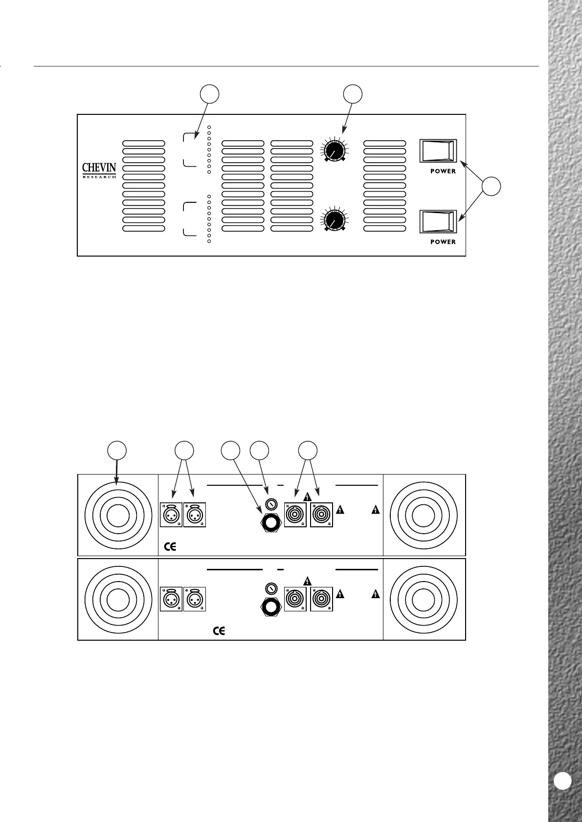
1 Variable Speed Fans.
The fans run when the amplifier is switched on.
They spin at variable speeds depending on
the level of signal and ambient temperature.
2 Mains Input.
Mains input is via a fixed, high current 3-core mains
cable, one per channel. Wiring is as per standard
European colour coding.
3 Mains Fuse.
One per channel. Correct fuse rating indicated on the
back panel legend.
4 Output Connectors.
Two Neutrik Speakon sockets per channel.
5 Input Connectors.
One male and one female XLR connector per
channel, wired in parallel with each other.
They may be used in balanced or unbalanced mode.
Pin wiring indicated on the legend.
A5000/A6000
1 Power Switches.
These control the mains power supply. (1 per
channel).
2 Output Controls.
These control the output level or gain.
3 Output Bargraph.
■ Power LED: The bottom green LEDs. Illuminates
when the unit is ON.
■ Output Voltage LEDs: The column of green LEDs
above the Power LEDs.These give an indication
of output voltage. Output power will be
determined by load impedance. llumination of the
70V LED indicates imminent clipping.
■ Clip LED: The top red LEDs. It illuminates when
the amplifier is being driven into clip and
indicates that the SoftClip system is active. If the
Clip threshold is exceeded, the intensity of this
LED provides an indication of the degree of
overdrive.
A5000/A6000
11
FRONT PANEL
BACK PANEL