A750/A1000/A1500/A2000/A3000
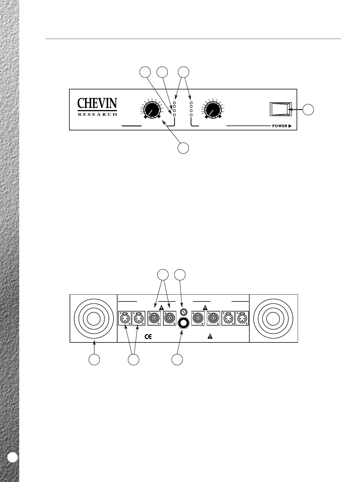
1 Power Switch.
This controls the mains power supply to the
amplifier.
2 Output Controls.
These control the output level or gain of each
channel.
3 Power LEDs.
The top green LEDs. 2 per channel. They illuminate
when the unit is ON.
4 Clip LEDs.
These are the red LEDs, one per channel. They
illuminate when the unit is being driven into clip
and indicate the SoftClip system is active.
5 Signal LEDs.
The bottom green LEDs, one per channel.
They illuminate when signal is present.
A750/A1000/1500/12000/A3000
8
1 Variable Speed Fans.
The fans run when the amplifier is switched on.
They spin at variable speeds depending on the level
of signal and ambient temperature.
2 Mains Input.
Mains input is via a fixed, high current 3-core mains
cable. Wiring is as per standard European colour
coding.
3 Mains Fuse.
Correct fuse rating indicated on the back panel
legend.
4 Output Connectors.
Two Neutrik Speakon sockets per channel.
5 Input Connectors.
One male and one female XLR connector per
channel, wired in parallel with each other.
They may be used in balanced or unbalanced mode.
Pin wiring indicated on the legend.
FRONT PANEL
BACK PANEL