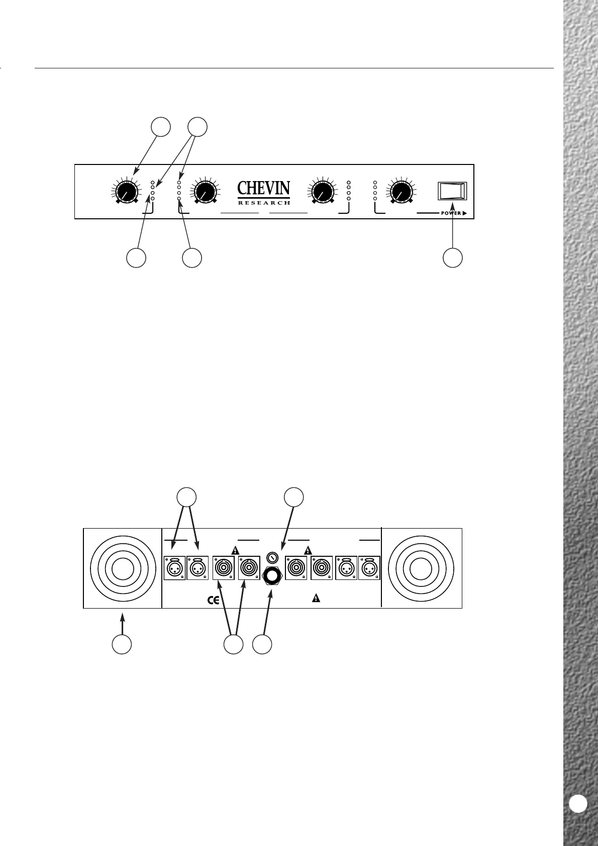
1 Variable Speed Fans.
The fans run when the unit is ON. They spin at
variable speeds depending on the level of signal and
ambient temperature.
2 Mains Input.
Mains input is via a fixed, high current 3-core mains
cable. Wiring is as per standard European colour
coding.
3 Mains Fuse.
Correct fuse rating is indicated on the back panel
legend.
4 Output Connectors.
Q6 amplifiers have two pairs of parallel-connected
Neutrik Speakon sockets on the outputs, each pair
carrying the output of two channels.
5 Input Connectors.
Q6 amplifiers have one female XLR connector per
channel, which may be used in balanced or
unbalanced mode. Pin wiring as indicated on the
legend.
Q6
1 Power Switch.
This controls the mains power supply.
2 Output Controls.
These control the output levels or gain of each
channel.
3 Power LEDs.
The top green LEDS, 2 per channel. They illuminate
when the unit is ON.
4 Clip LEDs.
The red LEDs, one per channel. They illuminate
when the amplifier is being driven into clip and
indicate that SoftClip system is active.
5 Signal LEDs.
The bottom green LEDs, one per channel. They
illuminate when signal is present.
Q6
9
FRONT PANEL
BACK PANEL
CH. C1+ HOT 1- COLD
CH. C1+ HOT 1- COLD
CH. C1+ HOT 1- COLD