21
MI300T 220V
qj
Ensure the machine is unplugged from the mains, and then wait 2 minutes before carrying out maintenance work. Inside the
machine, voltage and current levels are high and dangerous.
• Prior to any work on the machine, turn the air supply o and depressurise the circuit of the machine.
• Make sure to purge the lter of the dehumidier located at the back of the machine regularly.
• The device is tted with a balance system designed for easier handling. However, it is not recommended to leave the clamp hanging at the end of
the cable of the balancing system for prolonged periods of time as it might increase wear. Do not drop the clamp repetitively or it might damage the
balancing system.
• It is possible to adjust the tension of the balancing system spring using the spanner provided.
•The level of the cooling liquid is important for the machine to work correctly. It must always be between the «minimum» and «maximum» marks on
the machine. Regularly check the level and top-up when needed.
• It is recommended to renew the cooling liquid every 2 years.
• All the welding tools will wear o with use. Ensure that these tools are clean to get the best results.
• Prior to using the pneumatic clamp, check the condition of the electrodes/caps (regardless if they are
round or at). If that is not the case, clean them using sand paper (thin grain) or replace them (see
explanation on the machine).
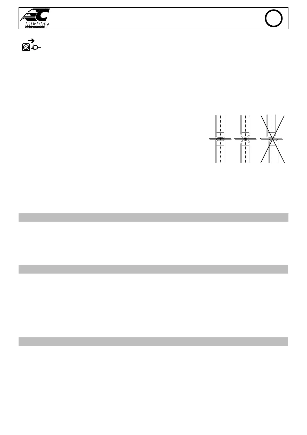
• To ensure an ecient welding spot, it is necessary to replace the caps every 200 spots. In order to
do so :
- Remove the caps using the caps removing wrench (ref. 050846)
- Fit the caps and apply contact grease (ref. 050440)
• Caps type A (ref : 049987)
• Caps type F (ref : 049970)
• Caps bevelled (ref : 049994)
Warning : the caps must be perfectly aligned. If this is not the case, check the alignment of the
electrodes (cf. chapter «Assembly and replacement of the arms» P. 48)
A
A
F
F
A
A
• Prior to using the gun, check the condition of the dierent tools (star, single sided electrode, carbon electrode...) and clean or replace if required.
• Remove regularly the casing and any excess of dust. Take this opportunity to have the electrical connections checked by a qualied person, with
an insulated tool.
• Regularly review the condition of the power cable and welding connection cables. In case of visible signs of damage, organise for them to be
replaced by the manufacturer or a qualied technician.
• Ensure the vents of the device are not blocked to allow adequate air circulation.
USE OF THE GALLOWS
• The operator must properly ll the coolant canister with coolant before use.
• The use of the bracket is strictly reserved to support the clamp during welding operations.
• Under no circumstances must the jib crane be used as a lifting or other means, as there is a risk of tipping the jib crane trolley assembly.
INSTALLATION – PRODUCT OPERATION
Only qualied personnel authorised by the manufacturer should perform the installation of the welding equipment. During the installation, the
operator must ensure that the machine is disconnected from the mains. Connecting generators in serial or in parallel is forbidden.
EQUIPMENT DESCRIPTION (FIG-1)
This machine is designed to carry out the car body repair operations described below :
- spot welding on sheets using a pneumatic clamp,
- welding of sheets using a gun,
- welding of nails, rivets, washers, studs, mouldings,
- repair of bumps and impacts (hail impacts with the pliers option).
1- SD card reader 6- Power-on circuit breaker
2- Interface (MMI) 7- Power cord
3- Cooling unit 8- Filling cap
4- Overhanging arm locking support 9- Cooling liquid gauge
5- Regulator
DESCRIPTION OF THE G CLAMP (FIG-2)
1- Arm locking/unlocking lever 7- Locking latch
2- Interchangeable arm 8- Gyro lock/unlock mechanism
3- Gyroscope 9- Over-opening button
4- Pneumatic body 10- Spot welding button
5- Over-opening electrode 11- Remote settings button
6- Side handle
Clamp opening : push the button (FIG 2 - 10), the opening of the clamp can be released. The electrode retracts in the clamp leaving a space of
80 mm to access the welding area instead of 20 mm when not in use.
EN