17-4
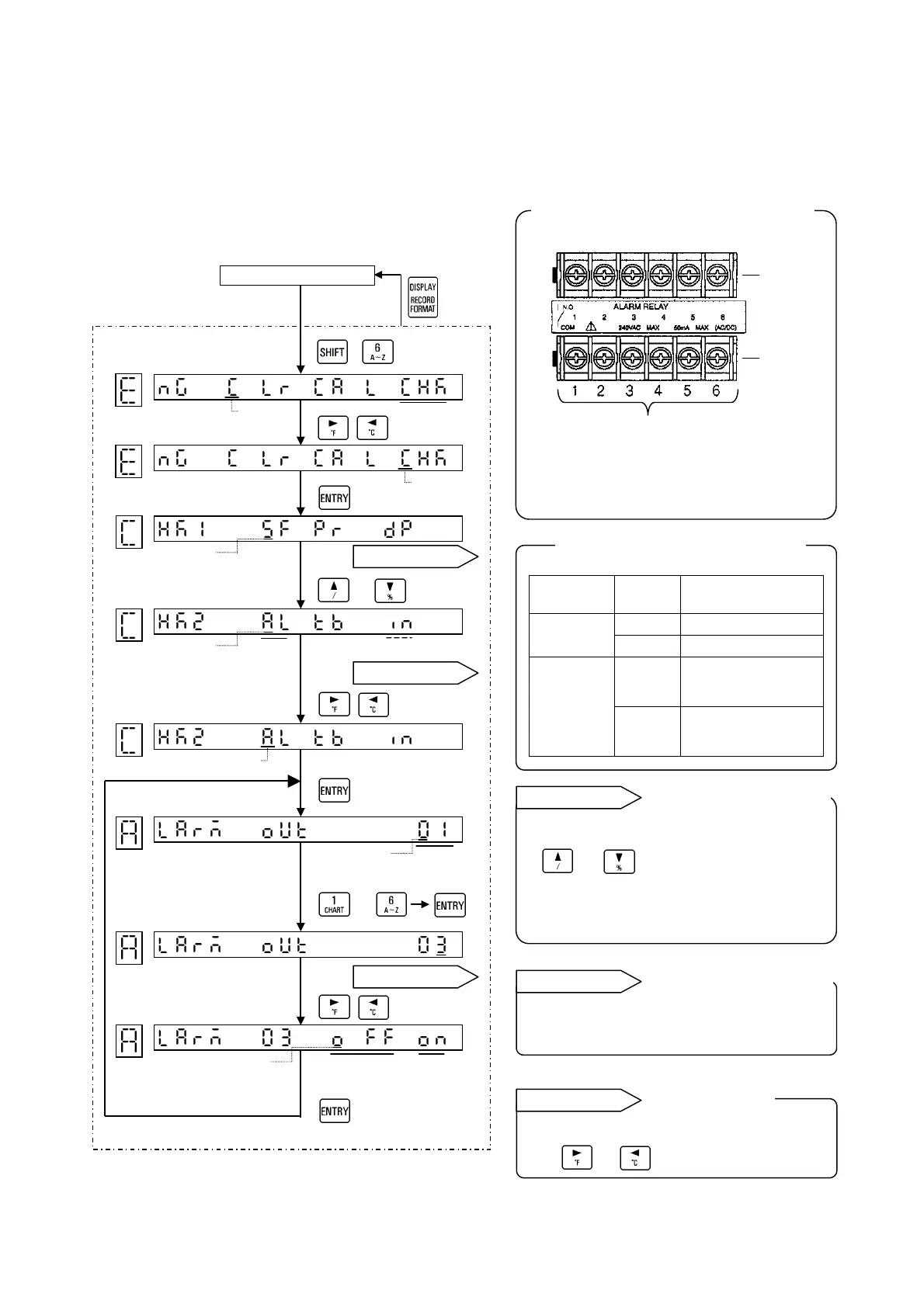
17.4. Alarm Output Check
This check applies to the instrument with an alarm output function (option) only. Alarm outputs can be
checked by outputting either shorted (ON) or open (OFF) signal from specified alarm output terminals.
1. Check flow chart
<Example> Alarm output No. 03 check
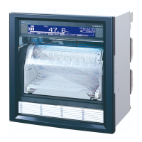
Operation screen
* The above figure shows MOS relay
output and CE mechanical relay 'a'
contact output.
Output
Output
condition
N.O-COM
OFF
Higher than 10MΩ
MOS
relay
ON
Lower than 50Ω
OFF
Higher than 10MΩ
Mechanical
relay
('a' and 'c'
contact
common)
ON
Lower than 0.1Ω
CHK1 and CHK2 are switched by
or key.
CHK2 can be selected only when options
(alarm output + remote contacts or
communications interface) are added.
Refer to the separate instruction manual
for [communications interface].
The condition (OFF/ON) being selected
by or key is output.
[Engineering mode]
Check
Cursor
Longer
than 3sec.
[Selecting check]
[To CHK1 display]
Cursor
Cursor
[Selecting alarm]
[To output number display]
Longer
than
2sec.
( + )
[To CHK2 display]
Cursor
[Programming output
number]
[Selecting output condition]
Alarm
Communication
or
Reference 1
Reference 2
Cursor
Cursor
Output
number
Reference 3
Shorted
(ON)
Open
(OFF)
to
Cursor
N.O
terminals
COM
terminals
Output numbers
Alarm output terminals (No. 01 to No. 06)
Resistance value across terminals
CHK1 and CHK2 displa
selection
Reference 1
Communications interface
check.
Reference 2
Out
ut condition
Reference 3
 Loading...