E1
SAFETY PRECAUTIONS
INST.No.KP3-41-3
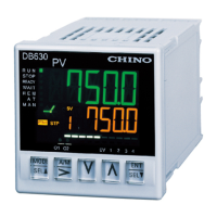
Digital Program Controller / Setter
KP1000 / KP2000 / KP3000
Instruction Manual
for Installation
Thank you for purchasing the KP1000 / KP2000 / KP3000.
Before operating the product described in this user’s manual, please
take note of the following points regarding safety.
Be sure to keep this manual nearby for handy reference.
Please read the "Terms and Conditions" from the following URL
before ordering or use:
https://www.chino.co.jp/support/guarantee/index.html
NOTICE
Be sure that the user receives this manual before the product is
used. Copying or duplicating the manual in part or in whole is
forbidden. The information and specifications in the manual are
subject to change without notice. Considerable effort has been
made to ensure that this manual is free from inaccuracies and
omissions. If you should find an error or omission, please contact
your nearest CHINO office. In no event is CHINO liable to anyone
for any indirect, special or consequential damages as a result of
using this product.
This manual only explains the handling precautions, mounting,
wiring, input type, list of parameters and main specifications.
For instruction manual other than this document, go to CHINO
homepage https://www.chino.co.jp, register for a membership, and
download. See KP1000, KP2000 or KP3000 Instruction manual
(General) for the detail handling procedures etc.
Unpacking
Check the following items when removing the KP1000, KP2000, and
KP3000 from its package:
Name Q'ty Remarks
Mounting Bracket 2 (1 set) For panel mounting
Instruction Manual
(installation)
1 This Manual
Contact protection
element
1
ttached to ON-OFF servo type
specifications only
A protective film is attached to the front console of this unit to protect
the surface. After installation and wiring are complete, peel off the film
before use.
The use of this product in a manner not specified by the manufacturer
will impair its built-in safety features.
WARNING
PRECAUTION
Quick Start Guide
From installation to Input type and Program pattern setup
Step 1. Mount..................................Page E3
Step 2. Wire………………………….Page E4
Step 3. Set Input type……………..Page E13
Step 4. Set the Program pattern...Page E13
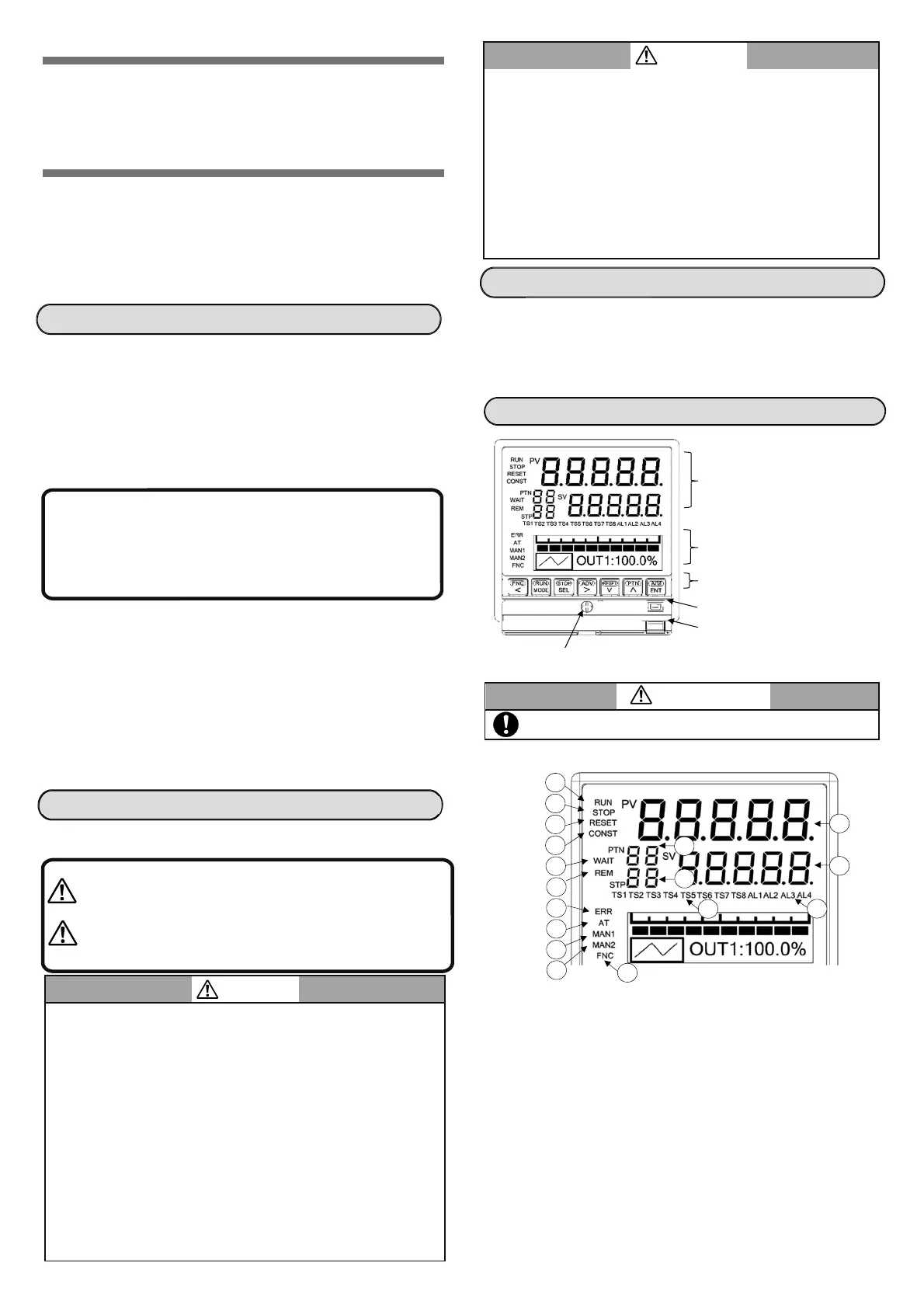
Part names and functions
Upper display
(1) PV (KP1000/KP2000)
Displays PV (measurement value).
(2) SV
Displays SV (setting value).
(3) PTN No.
Displays the pattern number that is being selected.
Blinks when PTN is changed.
(4) STP No.
Displays the step number that is being executed.
During real temperature compensation operation, the
numeral of the No. blinks.
(5) RUN
Lights during RUN status.
Blinks during FAST status.
WARNING
(1)Before supplying the power to the product, check that the wiring is
correct and power supply voltage matches with the rated voltage
etc.
(2)This product does not have a power supply switch. Install a circuit
breaker that matches the rating specifications in the power supply
of the product.
(3)To prevent electric shock, provide the terminal of the product with
safety measures such that the user will not be able to touch the
final product directly.
(4)
This product is designed as a general-purpose product for general
industrial products. It is not intended for use in human-life and
property related applications such as nuclear and radiation related
equipment, medical equipment, aerospace equipment, railroad, and
marine transportation equipment. To use this product for equipment
that requires high quality and safety that affects human-life and
property, design and install the protection and safety circuits to
ensure safety at your own responsibility.
(5)Do not put your hand and tool inside the product. You may get an
injury or an electric shock.
WARNING
(6)If there is offensive smell, strange noise or smoke or if the
temperature increases abnormally, it is very risky hence cut off the
power supply immediately and contact the dealer or nearest
CHINO's office.
(7)If repairing or remodeling is necessary, contact the dealer or
nearest CHINO's office. Only the service engineers appointed by
our company will change the parts, do the repairing and
remodeling.
(8)In order to use the product correctly and safely, follow this
instruction manual. Please understand beforehand that our
company will not at all be responsible for any claims for injury,
damage, and passive damage due to wrong use of the product.
PRECAUTION
This internal rack fixing screw is used at the time of
maintenance.
Warnings are indicated when there is a risk of
operator death or serious injury. Information is
provided regarding how to avoid this risk.
Cautions are indicated when there is a risk of
operator injury, damage to the product, and/or
damage to peripherals. Information is provided
regarding how to avoid this risk.
Upper display
Lower display
Key switch panel
Engineering port
Lower cover
Internal rack fixing screw
5
3
1
2
6
7
8
9
10
11
12
13
16
4
14
17
15
 Loading...