.15.
.14.
Air Circuit Breaker
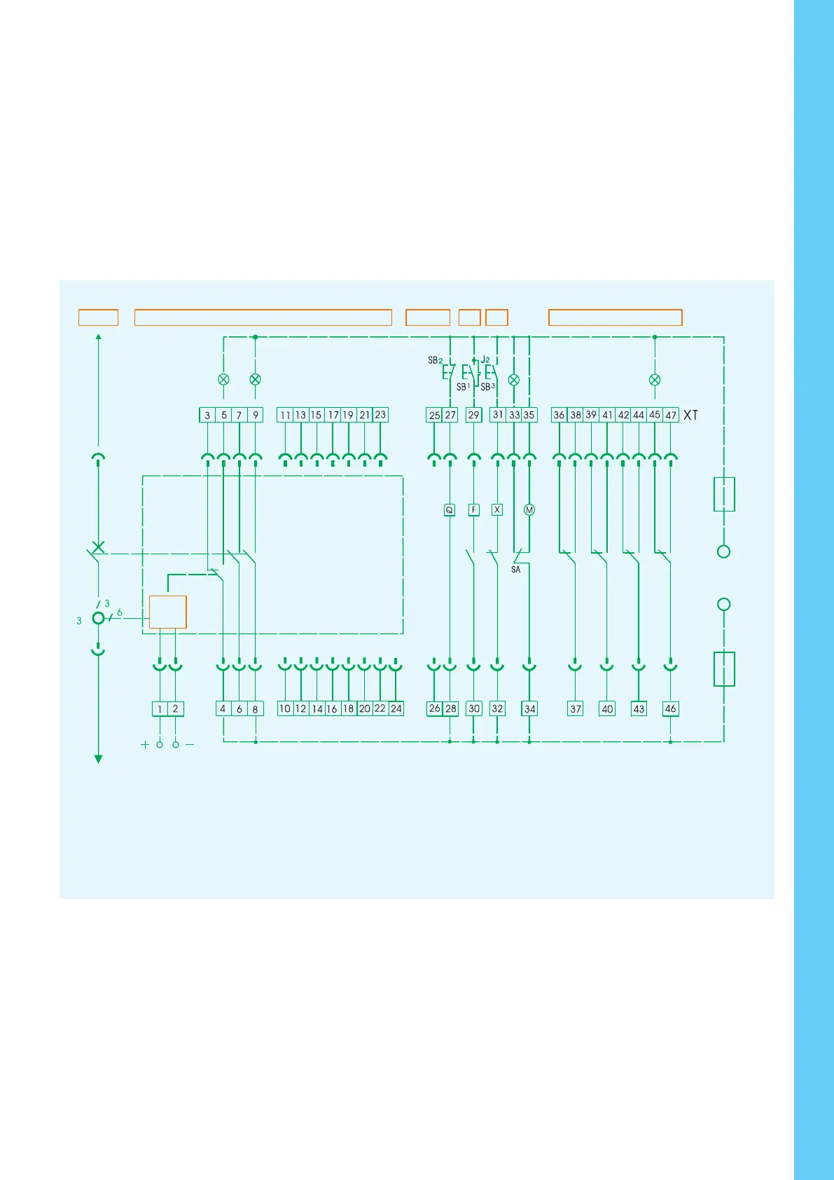
Note: If control voltage of Q, F, X is different from each other, they can be connected to different power. If model ST intelligent release is DC, it
must pass through U1 and U2 before directly connected to terminal 1 or 2.Circuit explanation for signal output
a.Broken-line parts shall be provided by customers.
b.Terminals 6# ~7# can output NC (normal close) contact if that is required by users.
c.Terminal 35# can be directly connected to power (automatic pre-storing energy), alternatively connect power after connecting NO button (manual-
controlled pre-storing energy).
In order to avoid the damage to shunt release and closing electromagnet, one group of NO (shunt release) or NC (closing electromagnet) contact
should be separately connected to the control circuit.
6.2 NA1-2000, 3200, 4000, 6300
Hl1: Failure indicator
HL2: Close indicator
HL3: Energy storage indicator
SB1: Under-voltage button
SB2: Shunt button
SB3: Close button
Q: Under-voltage release
F: Shunt release
X: Close release
M: Energy storage motor
DF1-F4: Auxiliary switch
# #
1 , 2 : Auxiliary power input(DC24V)
# # # #
3 ,4 ,5 : Fault trip contact output(4 common terminal,
contact capacity AC230V,5A
# #
6 , 7 : to be connected with current transformer(N/O auxiliary
contact, capacity AC400V, 1A,when no current transformer)
# #
8 ,9 : Making indicator(capacity AC400V,1A)
# #
10 , 11 : communication output
# #
12 , 13 : Signal alarm of load 1 output
# #
14 , 15 : Signal alarm of load 2 output
# #
16 , 17 : Making signal output
# #
18 , 19 : Closing signal output
#
20 : Communication shield ground line
# #
21 ~24 : Voltage signal input of phase N,A,B,C
# #
25 , 26 : Auxiliary contact (capacity:AC230V,5A)
# #
27 ,28 : Under-voltage release
# #
29 ,30 : Shunt release
# #
31 ,32 : Closing release
# # #
33 ,34 ,35 : Energy storage motor
# #
36 ~40 : Auxiliary contact (capacity:AC230V,5A)
Note: Dashed is to be connected by users.
13
23
10
+ -
1 4 6
8
21
12 14 16
253 5
40
15
11
37
36
97
27
29 31 33
22 26 30 34
35
DF1
24
39
38
2
M
SB3SB1 SB2
▲
TA
XT
XT
19
X
F
Q
3228
DF2 DF3
18 20
17
HL1
ST-DP
Profibus-DP
Device
HL3
D01
DC24V
12
12
L
-
21
+
ST201
1716
- +
15
+
13 14
+
N
-
PE
ST-4
D03
16 17
D02
1413 15
9873 4 5 6
+
COMD11 D13D12
18 19
- +
10 11
FU
N
PE
L1
SA
DC24V
HL2
Power
module
Intelligent
controller
Main circuit
Intelligent controller
Auxiliary switch
Motor-driven
break
Emergenay
break
Motor-driven
make
Fault indicator
Power module
Green
Red
Fig 2: Communication type (H type)
Sb1 Shunt button SB2 Under-voltage button SB3 Making button SA
Q Under-voltage release or under-voltage time-delay release F Shunt release
X Closing release M Energy-storage motor XT Connection terminal
Position switch
Main circuit
Over-current release
motor
driven
break
motor
driven
close
auxiliary switch
Emergent
disconnection
Open
Energy storage
Power
CloseFailure
Processing
unit
Intelligent Controller
Intelligent release power("1"connect positive pole,and"2"connect negative pole for direct current)
110V
230V
~400V
~
_
~
_
FU
FU
Fig 1: Standard type (M type)
 Loading...