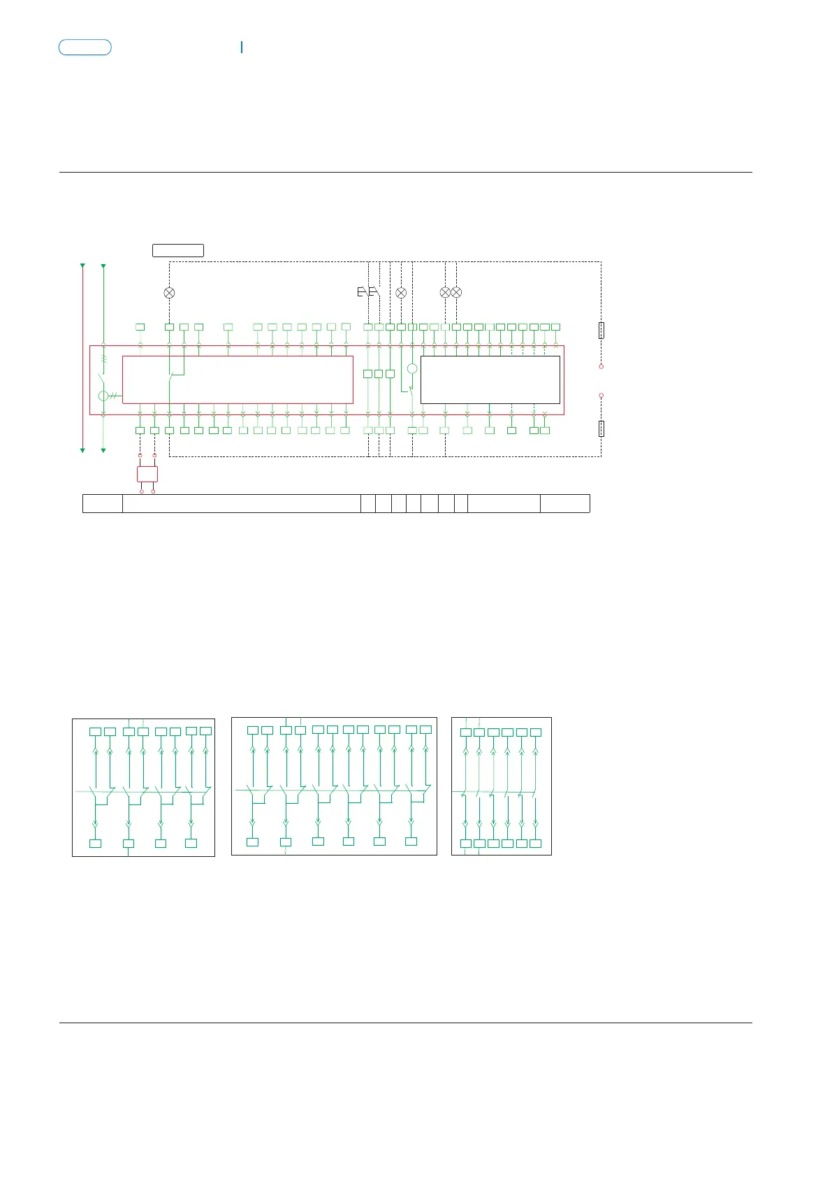
Connection diagram for the secondary circuit of NA8G-1600 with standard type intelligent controller Connection diagram for the secondary circuit of NA8G-3200 to 6300 with standard type intelligent controller
6. Secondary circuit wiring
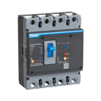
Air Circuit Breaker
NA8G
Air Circuit Breaker
P-020
NA8G
P-019
4
QF
TA
N
5
35
33
7
27
DC24V
S
8
FU
52
56
43
37
55
FU
50
53
54
+
M
38
36
HL3
HL4
47
L2(N)
L1
31
41
29
25
21
23
13
17 19
15
9
10
11
21
XT
XT
3
32
34
Q/QY
SA
HL2
28
F
26
30
DT
SB2 SB1
2422
20
16
14
18
12
SAL
6
HL1
-
A B C
Fault indicator
Intelligent controller
Breaker body
Control power
40
49
46
39
42
44
45
48
51
Auxiliary contact available for users
OFF
indication
ON
indication
Energy
storage
indication
AC auxiliary contact for standby application
Under
voltage
Power
-driven
energy
storage
Open
Close
Main circuit
Intelligent controller
F——shunt release
M——energy storage motor
HL1~HL4——indicator light
S——power module
F——shunt release
M——energy storage motor
HL1~HL4——indicator light
S——power module
DT——closing electromagnet
SA——travel switch
SB1~SB2——pushbutton
QF——breaker
DT——closing electromagnet
SA——travel switch
SB1~SB2——pushbutton
QF——breaker
Q/QY—under voltage release
AX—auxiliary contact
XT—connection terminal
SAL—sensitive switch
Q/QY—under voltage release
XT—connection terminal
AX—Auxiliary contact
SAL—sensitive switch
FU—fuse
TA—current transformer
FU—fuse
TA—current transformer
# #
1 and 2: input (terminals) for intellectual controller auxiliary power supply
# # # #
4, 5 and 6: faulty tripping contact output ( 5 is the common terminal, AC250V 5A)
# #
1 and 2: input (terminals) for intelligent controller auxiliary power supply
# # # #
4, 5 and 6: faulty tripping contact output ( 5 is the common terminal, AC250V 5A)
4
QF
TA
N
5
35
33
7
27
DC24V
S
8
FU
52
56
43
37
55
FU
50 53
54
+
M
38
36
HL3
HL4
47
L2(N)
L1
31
41
29
25
21
23
13
17 19
15
9
10
11
21
XT
XT
3
32
34
Q/QY
SA
HL2
28
F
26
30
DT
SB2 SB1
24
22
201614 18
12
SAL
6
HL1
-
A B C
Frame 3200, 6300 shell controller power supply: DC220V,DC110V;
3200 and 6300 frame controller power supply: AC230V and AC400V
40
49
46
39
42 44 45
48
51
Fault indicator
Control power
Intelligent controller
Breaker body
Auxiliary contact available for users
OFF
indication
ON
indication
Energy
storage
indication
AC auxiliary contact for standby application
Under
voltage
Power
-driven
energy
storage
Open
Close
Main circuit
Intelligent controller
AX
AX
The auxiliary contact modes for customer use
The auxiliary contact modes for customer use
Ⅰ Four switch contact
(acquiescence)
Ⅱ Six switch contact
Ⅲ Three open and
three close contact
Ⅲ Four open and
four close contact
Ⅳ Five open and
five close contact
Ⅰ Four switch contact
(acquiescence)
Ⅱ Six switch contact
Notes: 1. Four switch contact is the normal auxiliary contact mode.When special order is made for alternating current, six switch contact,
three open and three close contact can be selectedadditionally. Four switch contact is the only mode in case of direct current.
# # # #
2. When the controller voltage is AC230/400V, it can be directly put into 1 and 2; if the voltage is DC220/110V, it has to be put into 1 and 2 after
the power module output DC24V.
3. The wiring for the part indicated by dashed lines shall be made by users.
Notes: 1. Four switch contact is the normal auxiliary contact mode. When special order, six switch contact, four open and four close contact, five open
and five close contact can be selected additionally.
# #
2. When the controller voltage of frame 3200 and 6300 is AC230V/400V, it can be directly put to 1 and 2; if the voltage is DC220V/110V, it has to be
# #
put to 1 and 2 after the power module outputs DC24V.
3. The wiring of the part indicated by dashed lines shall be made by users.
37
38 39
40
41 42
43
44 45
46
47 48
37
38 39
40
41 42
43
44 45
46
47 48
49
50 51
37
38
39 43 45 47
40 42 44 48
46
41
52
53 54
37
38
39 43 45 4947 51
40 42 44 48 52
46 50
41 37 39 43 45 47
38 40 42 44 48
46
41 49 53 51 55
52 56
50 54
37
38 39
40
41 42
43
44 45
46
47 48
37
38 39
40
41 42
43
44 45
46
47 48
49 52
50 5351 54