Rated current range [Ii]
Error
Line current [I]
Operating Characteristics
≤0.85Ii
>1.15Ii
no-action
action
(2~15)In
+OFF(Power off)
±15%
4
6
8
10
2
3
Ii
12
15
Off
(A~J)In
+OFF(Power off)
±10%
<0.9Ig
>1.1Ig
2
I T OFF
2
I T ON
I>J
2
I T ON
I≤J
±15%
7.6.4 Single-phase earthing fault protection
7.6.3 Short-circuit instantaneous overcurrent protection
Rated current range [Ig]
Error
Line current [I]
no-action
time-delay action
0.1 0.2 0.3 0.4
0.1 0.2 0.3 0.4
2 2
anti-time-limit delay I Tg=(J) tg
Operating time [tg(s)]
Time (delay) error
Meaning of Ig
Rated current In
In≤400A
400A<In≤1200A
1200A<In
A
0.3
0.2
500A
B
0.3
0.3
640A
C
0.4
0.4
720A
D
0.5
0.5
800A
E
0.6
0.6
880A
F
0.7
0.7
960A
G
0.8
0.8
1040A
H
0.9
0.9
1120A
J
1.0
1.0
1200A
Note
×In
×In
×I n
.4
.4
.3
. 2
.1
.1
.2
.3
X
2
I t
Tg
(s)
Ig
E
F
G
H
JA
B
C
D
OffON
Example 3: If it is known that the single-phase earthing
protection setting current for the intelligent controller with
rated current of In=800A is as the setting position of C, the
tripping time is set as the inverse time limit 0.4s.
Now there is a failure in the circuit, the circuit current I=400A,
then the actual tripping time can be worked out; it can be seen
from the table that the result is
C=0.4
Ig=C×In=0.4×800=320A
So I=400A>1.1Ig
2 2
According to the formula I T =(J) t
g g
2 2
(400) ×T =(1.0×800) ×0.4
g
T =1.6s
g
Note: For the intelligent controller, the current settings for the
long time-delay and the short-circuit short time-delay and the
intantaueous overcurrent protection should not come across
each other, and the condition of I <Isd<Ii must be ensured.
R
Rated control supply voltage Us(V)
Operating voltage (V)
Power dissipation (W)
Closing time
AC230 AC400
(0.7~1.1)Us
200VA
50±10ms
AC230 AC400
(0.85~1.1)Us
200VA
50±10ms
DC220 DC110
200W
DC220 DC110
200W
8.2 Shunt release
After the shunt release is energized, the breaker is switched off
instantaneously to allow remote operation.
8.3 Closing electromagnet
After the motor-driven energy storage is ended, energizing the
closing electromagnet will make the energy storage spring force of
the operating mechanism to be released instantaneously to rapidly
switch the breaker on.
Rated operational voltage Ue(V)
Operating voltage(V)
Reliable switching voltage(V)
Reliable not-switching voltage(V)
Power dissipation(W)
AC230 AC400
(0.35~0.7)Ue
(0.85~1.1)Ue
≤0.35Ue
20VA
Rated control supply voltage Us(V)
Operating voltage (V)
Power consumption (W)
Breaking time
Under-voltage release
(Inm=1600A)
Under-voltage release
(Inm=3200A, 6300A)
Shunt release
(Inm=1600A)
Shunt release
(Inm=3200A, 6300A)
Closing electromagnet
(Inm=1600A)
Closing electromagne
(Inm=3200A, 6300A)
8. Accessories
Operating characteristic:
Operating characteristic:
NA8G
Air Circuit Breaker
P-034
P-033
NA8G
Air Circuit Breaker
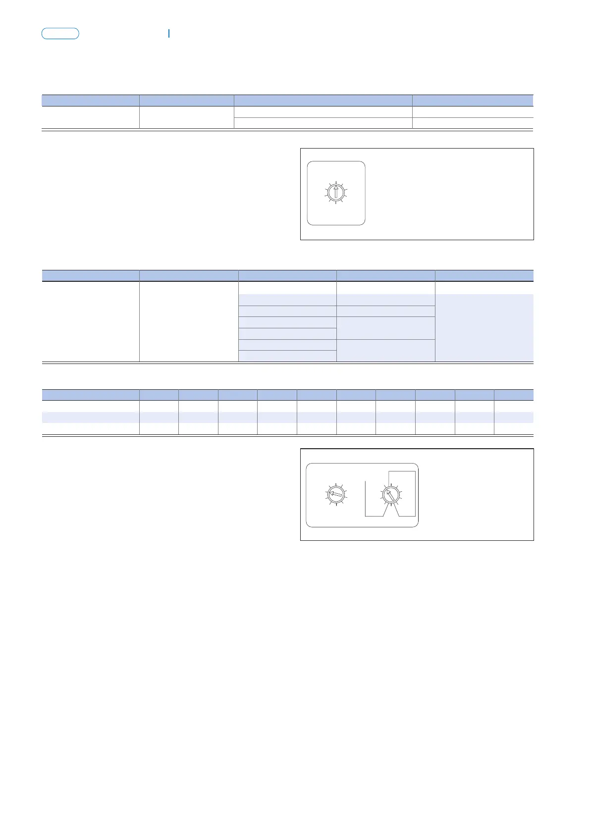
Explanation for parameter setting
Current of short-circuit instantaneous over current protection:
Ii=[2-3-4-6-8-10-12-15-OFF]×In, optional.
The method for setting the current of short-circuit
instantaneous
overcurrent protection is similar to that for long time-delay
overcurrent protection setting. As shown in the figure, the
instantaneous overcurrent protection current setting value is
8In.
Explanation for parameter setting
Current of single-phase earthing protection : Ig=(A-B-C-D-E-
F-G-H-J)×In, optional.
There are nine setting positions for the protective delay
tripping time, wherein 4 settings represent the definite-time
2
limit characteristic (i.e., I t OFF), 4 settings the inverse-time
2
limit characteristic (I t ON), and 1 setting the function of
closing the single-phase earthing protection (X).
When the tripping time is set as definite-time limit operating
characteristic (i.e., the arrow points at the OFF area), the
tripping time can be selected as tg=0.1s-0.2s—0.3s-0.4s-x
(i.e., the function of closing the single-phase earthing
protection).
When the tripping time is set as inverse-time limit operating
2
characteristic (i.e., I t ON), there are two cases:
① in the case of I>1.1Ig and I>J, the result of the automatic
changeover process is the definite-time limit operating
characteristic, tg=0.1s-0.2s-0.3s-0.4s;
② The case of the current meeting the condition of 1.1Ig<I≤J
represents the inverse-time limit characteristic and the actual
tripping time is calculated according to the formula
2 2
I Tg=(J) tg.
In the formula, I is the circuit current, Tg is the actual
operating time, J is the setting current, and tg is the setting
tripping time.The method for setting the parameter is similar
to that for long time-delay current protection. As shown in
the figure, the single-phase earthing protection current is
C×In,and the tripping time setting is tg=0.4s in the setting
2
position of inverse time limit (I t ON).
7.7 Explanation for auxiliary functions
a. Explanation for test functions
When onsite adjustment, periodical inspection or overhaul is
made with the controller supported by the breaker, breaking
several times is necessary by using the test functions of the
controller to check the cooperation of the controller and the
breaker. With the breaker on, press the test key, and the
intelligent controller will trip instantaneously to cut off the
breaker.
Note: ① This function can be used only when onsite
adjustment or overhaul for the breaker is made, and shall not
be used during the normal operation.
② Each time before the controller is switched on, it is
necessary to press the reset button in the upper position of
the controller panel so that the breaker can be switched on
again for operation.
b. Explanation for fault memory
The controller still has the function of fault memory after reset
or de-energized to keep a latest historical event for post
analysis. Only when there is a new fault again, the original
information is cleared with the current latest faulty data saved.
For the inquiry method, refer to the above explanation about
fault display.
7.8 Explanation for display function
When the rated current is greater than or equal to 400A, the
primary current shall not be lower than 0.4In for single phase,
and 0.2In for three phases for normal operation of the
breaker.
When the rated current is less than 400A, the primary current
shall not be lower than 0.8In for single phase,and 0.4In for
three phases for normal operation of the breaker.
Note: When the AC220V ST power module is energized, and
the voltage falls to AC120V, there will be no display on the
controller.
When the AC380V ST power module is energized, and the
voltage falls to AC200V, there will be no display on the
controller.
a. Current display Error range for current display: ±5%
b. Voltage display Error range for voltage display: ±1.5%
8.1 Under voltage release
When the under voltage release is not energized, neither
power-driven nor manual operation can make the breaker on.
For the under voltage release, there are two varieties:
instantaneous and time-delay operations.The time for the
under voltage time-delay release is Inm=1600A, the time can
be selected from but not adjusted in the range of 0 – 7s;
Inm=3200A or 6300A, the time can be selected from but not
adjusted among 0.5s, 1s, 3s, and 5s. When, within 1/2 delay
time, the power voltage returns to 85%Ue or above, the
breaker will not get disconnected.
Operating characteristic: