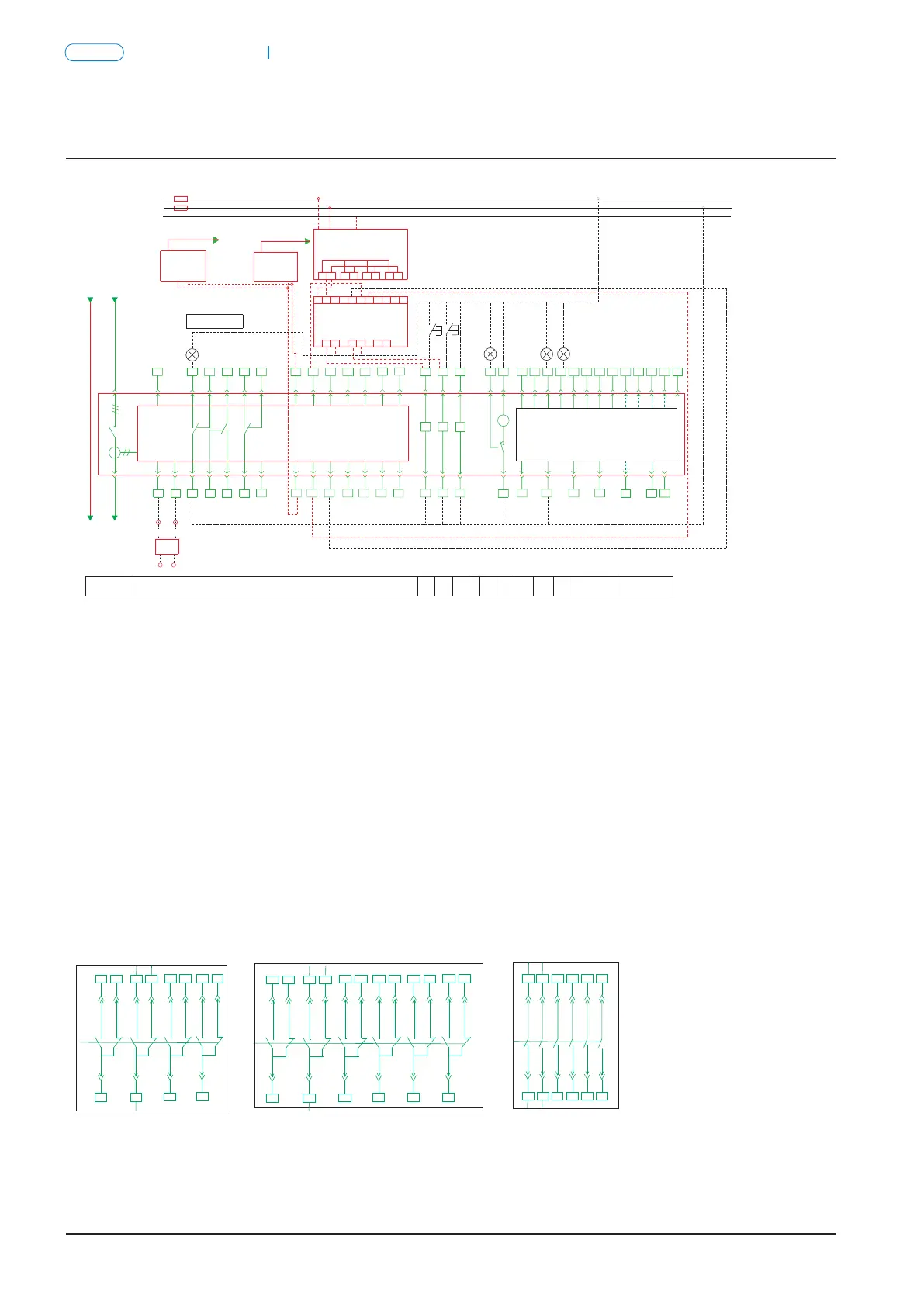
Connection diagram for the secondary circuit of NA8G-3200 and 6300 with multifuctional type itelligent controller.Connection diagram for the secondary circuit of NA8G-1600 with multifunctional type intelligent controller
Air Circuit Breaker
NA8G
Air Circuit Breaker
P-022
NA8G
P-021
-
3
S
1
+
XT
32
34
SA
37
28
F
26
55
4
53
XT
54
HL1
+-
1918
D12 D13D11
COM
+
6543 7 8
1513 14
D02
1716
D03
PSU-1 power module
PE
-
N
+
1413
+
15
+-
16 17
M
38
QF
TA
N
36
5
+
1 2
-
L
47
12
12
DC24V
30
DT
35
3331
41
7
29
25
27
21
23
DC24V
13
D01
17 19
15
9
PE
11
L1
PE
N
52
56
43
24
22
2
Green Red
module
Profibus-DP
FU
ST-DP
HL2
SB2
86
SAL
12
18
14
16 20
D14
SB1
HL3
HL4
A B C
D13 D15 D16
10
39
42 44 45
48
51
4946
40
50
Fault indicator
Q/QY
Intelligent controller
Breaker body
Auxiliary contact available for users
OFF
indication
ON
indication
Energy
storage
indication
AC auxiliary contact for standby application
Under
voltage
Power
-driven
energy
storage
Open
Close
Main circuit
Intelligent controller
DT——closing electromagnet
SA——travel switch
SB1~SB2——pushbutton
QF——breaker
PSU-1——power module (optional)
DT——closing electromagnet
SA——travel switch
SB1~SB2——pushbutton
QF——breaker
PSU-1——power module (optional)
F——shunt release
M——energy storage motor
HL1~HL4——indicator light
S——power module
AX—Auxiliary contact
F——shunt release
M——energy storage motor
HL1~HL4——indicator light
S——power module
AX—Auxiliary contact
Q/QY—under voltage release
XT—connection terminal
ST-DP —communication module
ST-DN—communication module
SAL—sensitive switch
Q/QY—under voltage release
XT—connection terminal
ST-DP —communication module
ST-DN—communication module
SAL—sensitive switch
FU—fuse
TA—current transformer
RU-1—relay module (optional)
FU—fuse
TA—current transformer
RU-1—relay module (optional)
1 and 2: input (terminals) for intelligent controller auxiliary power supply
#
3 PE
# # # #
4, 5 and 6: faulty tripping contact output ( 5 is the common terminal, AC250V 5A)
# # # #
7, 8 and 9: auxiliary contact output ( 8 is the common terminal, AC250V 5A)
# # # #
10, 11 and 12: auxiliary contact output ( 11 is the common terminal, AC250V 5A)
# #
14 and 15:RS485 communication interfaces (in case of communication type)
# # # # # #
16, 17, 18, 19, 26 and 27: programmable input/output points (DC110V 0.5A, AC250V, 5A)
# # # #
20, 21, 22, and 23: A, B, C, and N voltage signal output (in case of multifunction type) (maximum voltage AC400V)
# #
24 and 25: to be externally connected to the mutual inductor input
# #
:
32
34
Q/QY
SA
37
28
F
5553
54
M
38
36
47
30
DT
35
3331
41
29
52
56
43
HL2
SB2 SB1
HL3
HL4
39
42 44 45
48
51
4946
40
50
-
3
S
1
+
XT
26
4
XT
HL1
+-
1918
D12 D13D11
COM
+
6543 7 8
1513 14
D02
1716
D03
PSU-1 power module
PE
-
N
+
1413
+
15
+-
16 17
QF
TA
N
5
+
1 2
-
L
12
12
DC24V
7
25
27
21
23
DC24V
13
D01
17 19
15
9
PE
11
L1
PE
N
24
22
2
Green
Red
Profibus-DP
FU
ST-DP
module
86
SAL
12
18
14
16 20
D14
A B C
D13 D15 D16
10
Fault indicator
Breaker body
Intelligent controller
Frame 3200 and 6300 shell controller power supply: AC230V and AC400V
Frame 3200, 6300 shell controller power supply: DC220V,DC110V;
Auxiliary contact
available for users
OFF
indication
ON
indication
Energy
storage
indication
AC auxiliary contact for standby application
Under
voltage
Power
-driven
energy
storage
Open
Close
Main circuit
Intelligent controller
Device Net Device Net
ST-DN
module
ST-DN
module
RU-1 relay module RU-1 relay module
AX AX
The auxiliary contact modes for customer use
Ⅰ Four switch contact
(acquiescence)
Ⅰ Four switch contact
(acquiescence)
Ⅱ Six switch contact
Ⅲ Four open and
four close contact
The auxiliary contact modes for customer use
Ⅲ Three open and
three close contact
Ⅱ Six switch contact
Ⅳ Five open and
five close contact
controller power suply:AC220V, AC380V
controller power suply:DC220V, DC110V
Notes: 1. Notes: 1. Four switch contact is the normal auxiliary contact mode. When special order is made for alternating current, six switch contact,
three open and three close contact can be selected additionally. Four switch contact is the only mode in case of direct current.
2. The wiring of the part indicated by dashed lines to be made by users.
# # # #
3. When the controller voltage is AC230/400V, it can be directly put into 1 and 2; if the voltage is DC220/110V, it has to be put into 1 and 2 after the power
module output DC24V.
Notes: 1. Four switch contact is the normal auxiliary contact mode. When special order, six switch contact, four open and four close contact, five open and
five close contact can be selected additionally.
# #
2. When the controller voltage of the 3200 and 6300 shells is AC230V/400V, it can be directly put to 1 and 2;if the voltage is DC220V/110V, it has to be
# #
put to 1 and 2 after the power module inputs DC24V.
3. The wiring of the part indicated by the dashed lines shall be made by users.
37
38 39
40
41 42
43
44 45
46
47 48
37
38
39 43 45 47
40 42 44 48
46
41
37
38 39
40
41 42
43
44 45
46
47 48
49
50 51
52
53 54
37
38 39
40
41 42
43
44 45
46
47 48
37
38 39
40
41 42
43
44 45
46
47 48
49 52
50 5351 54
37
38
39 43 45 4947 51
40 42 44 48 52
46 50
41
37 39 43 45 47
38 40 42 44 48
46
41 49 5351 55
52 56
50 54