7.1.4 Display status of the operation panel
The state display of the operation panel is divided into stop state parameter display, running state
parameter display and function code parameter editing state display. The status display description is shown in
Table 7.5.
7.2 Example of panel operation
Various operations can be performed on the inverter through the operation panel, including reading read-
only parameters, modifying parameters, modifying set frequency, keyboard lock and unlock, user password
service, hexadecimal parameter setting method, monitoring running status parameters, etc. , enumerate relevant
examples as follows:
Example 1: Read read-only parameters
When reading read-only parameters, the parameters can only be read and cannot be modified. Taking
reading the value of the current bus voltage Fd.16 as an example, the operation steps are as shown in Figure
7.3, and the operation steps of other read-only parameters can be deduced by analogy.
Among them, "" means flashing, the same below .
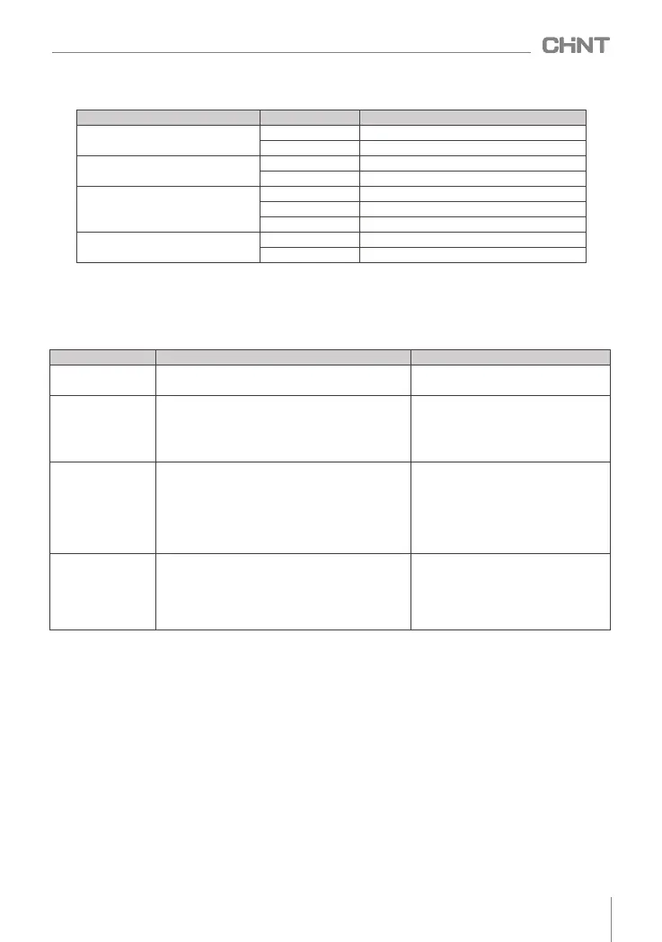
Table 7.5 Description of status display
Table 7.4 Description of Status Indicators
indicator light Display state
Indicates the current status of the drive
Running status indicator ( RUN/PRG)
Bright
off
Running direction indicator (F/R)
Bright
off
Running command channel indicator
light ( LOC/REM)
Bright
Operation panel control status
off
flashing
Fault indication ( FAULT)
Bright
off
Operating status
downtime
run in default direction
run in opposite direction
Terminal control state
communication control state
Fault state
normal status
Status Display
Instructions
Related parameters
Shutdown parameter
display
The inverter is in stop state, press SHIFT key, it can
cycle display different stop state parameters.
The stopped state parameters to be viewed
are defined by function code F7.07
Running parameter
display
When the inverter enters the running state, the RUN
/PRG indicator light on the panel is on, and the F/R
indicator light is on or off depending on the current
running direction. Press the SHIFT button to cycle
display the running status parameters.
The operating status parameters to be
viewed are defined by function codes
F7.05 and F7.06
fault display
When the inverter detects a fault signal, it enters the
fault alarm display state, at this time the FAULT light
is on and the fault code is displayed. The fault reset
operation can be performed through the STOP key on
the operation panel, the control terminal or the
communication command. If the fault persists, the
fault code will remain displayed.
Fault status parameters can also be
viewed through function code FE.06~
FE.12
Function code
editing
In the shutdown, running or fault alarm state, press
the PRG key to enter the editing state (if there is a
user password, see the description of F7.00), the
editing state is displayed in a two-level menu , and
the sequence is: function code group number →
function index number → function code parameter.
All editable parameters
027
NVF2G-S Series Inverter User's Guide
 Loading...