Operation and Description of Function Settings Chore-Tronics Model 16 & 8 Control
24
MT1554A 1/6/99
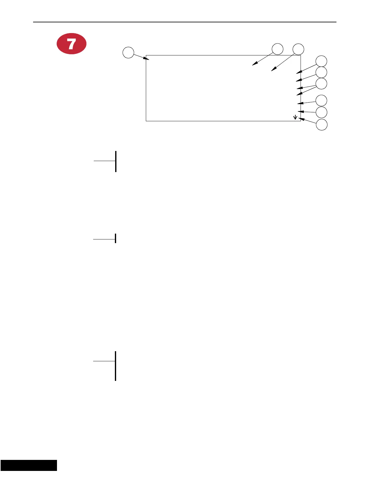
Alarms
The alarm output can be connected to external devices such as
sirens or dialers. The control itself will present a visual displa
in
screen “1” and screen “7”.
1. This will advise as to the status of the alarm system. The cursor will allow you
to make one of three choices:
• Enabled (or on)
• Disabled (or off)
• Test (which will sound your audible system and activate the visual
indicators
The statuses mentioned above refer to all alarms.
2. If there is an alarm present, this area will advise you as to what the alarm
condition is. The alarm possibilities are as follows:
• Maximum relative temperature
• Maximum temperature
• Minimum relative temperature
• Minimum temperature
• Sensor failure
• Failed potentiometer
• Maximum static pressure
• Minimum static pressure
• Static pressure sensor failure
• Power Off
If the alarm messa
e is a
roup of number’s, the problem deals with
the internal workin
s of the control and does not reflect problems
within
our house. If an alarm code appears in this space, notif
our local distributor and advise him of the code.
3. This is temperature difference relative to set temperature that you want to be the
high temp alarm.
4. This the result of adding the above value to your current set temperature. This
value is calculated automatically and is not editable.
Figure 13. Alarms Screen
*5#1*>+-
$;?5@)
,:5 87$)
,:!55
, 5 84$)
, !55
" @; !5
+? !5
3
2
4
5
7
1
8
9
6
{Note}
*
{Note}
*
{Note}
*
9/9/98