33
Parameter
Modbus
Parameter No.
ASCII is no longer
Supported Notes
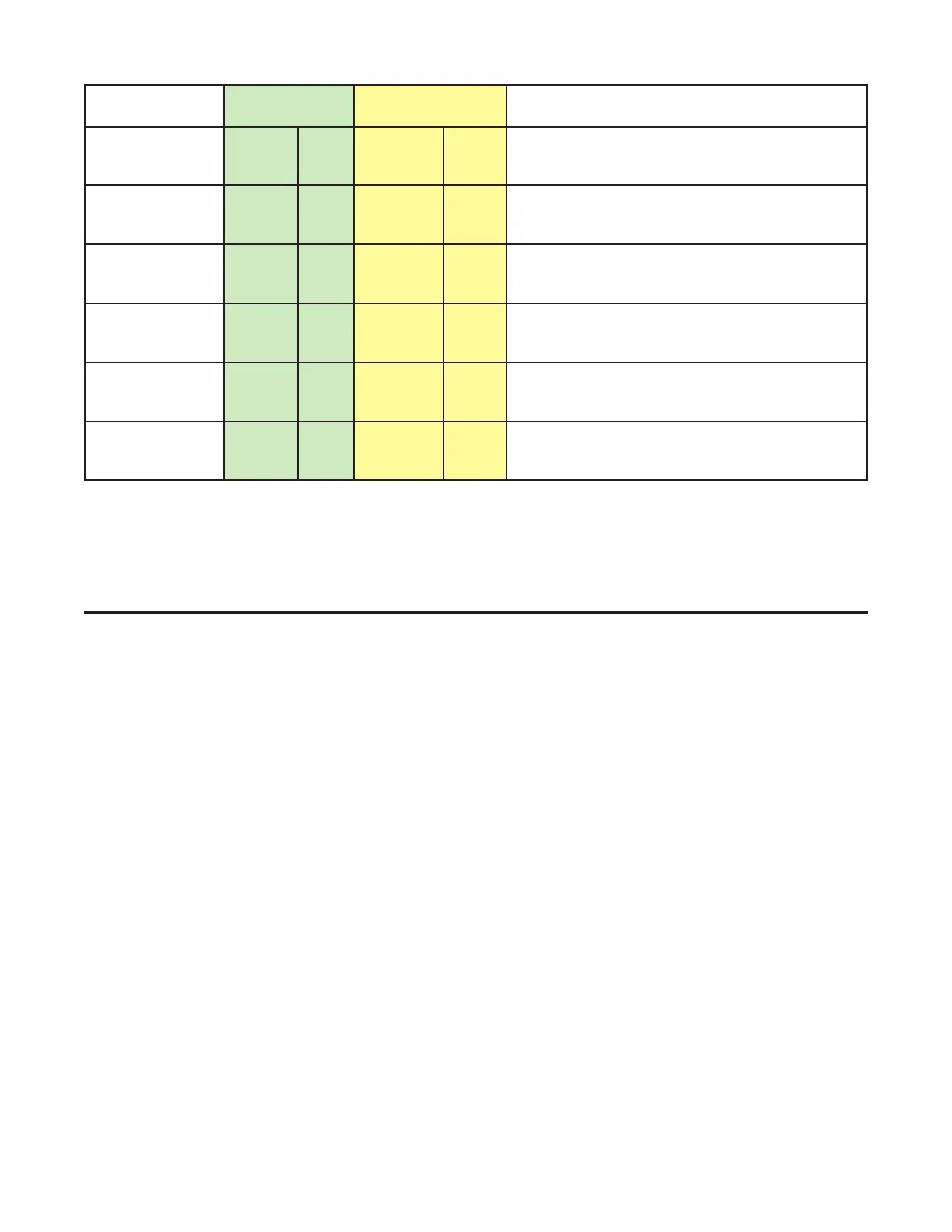
Option Slot 1
Re-transmit
output Maximum
2214 R/W Maximum scale value for retransmit output in
slot 1, -1999 to 9999.
Option Slot 1
Re-transmit
output Minimum
2215 R/W Minimum scale value for retransmit output in
slot 1, -1999 to 9999.
Option Slot 2
Re-transmit
output Maximum
2224 R/W Maximum scale value for retransmit output in
slot 2, -1999 to 9999.
Option Slot 2
Re-transmit
output Minimum
2225 R/W Minimum scale value for retransmit output in
slot 2, -1999 to 9999.
Option Slot 3
Re-transmit
output Maximum
2234 R/W Maximum scale value for retransmit output in
slot 3, -1999 to 9999.
Option Slot 3
Re-transmit
output Minimum
2235 R/W Minimum scale value for retransmit output in
slot 3, -1999 to 9999.
Notes:
ASCII is no longer supported.
Some of the parameters that do not apply for a particular configuration will accept reads and writes (e.g. at-
tempting to scale a Linear output which has not been fitted). Read only parameters will return an exception if an
attempt is made to write values to them.
These controllers are designed to control motorized
valves using a three point stepping Valve Motor Drive
(VMD) control algorithm. The 6040 1/16 – DIN VMD
Controller, 8040 1/8 – DIN VMD Controller and 4040
1/4 – DIN VMD Controller offer similar functionality in
three DIN sizes.
• Open loop valve control
• Two process alarms
• Valve position indication option
• Loop alarm
• MAN/AUTO Tuning
• RS485 Modbus communications option
• Remote setpoint option
• PC configuration option
Special Wiring Considerations for Valve
Motor Control
Valve Motor Drive (VMD) Controllers require two identi-
cal outputs to be assigned to position the valve. One
to Open and one to Close the valve. These outputs can
be two relays, two triacs, two SSR drivers or one dual
relay. The relay contacts are rated at 240VAC (120V
max for direct Valve Motor control – see CAUTION).
When using two relays (with SPDT change-over con-
tacts), it is recommended to interlock the relay wiring
as shown. This prevents both motor windings from be-
ing driven at the same time, even under fault condi-
tions.
9 6040, 8040 & 4040 VMD Controller – Model Group
 Loading...

