34
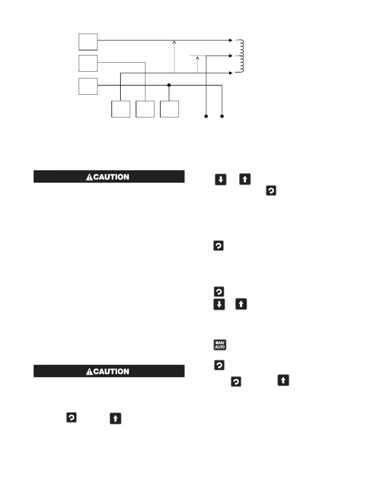
The windings of a valve motor effectively form
an Autotransformer. This causes a voltage dou-
bling effect when power is applied to either
the Open or Close terminal, causing twice the
supplied voltage at the other terminal. For this
reason, switching devices directly connected
to the valve motor must only be used up to half
of their rated voltage. The maximum motor
voltage when using the internal relays/triacs
is therefore 120V unless interposing relays are
used. Interposing relays or other devices used
to control the valve must themselves be rated
for twice the motor supply voltage.
6040, 8040 & 4040 VMD Controllers -
Configuration Mode
This mode is normally used only when the instrument is
configured for the first time or when a major change is
made to the instruments characteristics. The Configu-
ration Mode parameters must be set as required before
adjusting parameters in Setup Mode, or attempting to
use the instrument in an application.
Entry into the Configuration Mode
Adjustments to these parameters should only
be performed by personnel competent and au-
thorized to do so.
Configuration is entered from Select Mode
Hold down and press
to force the controller
into the Select Mode, then
Press
or to navigate to the Configuration
Mode option, then press .
Note: Entry into this mode is security-protected by the
Configuration Mode Lock Code. Refer to the Unlock
Code section for more details.
Scrolling through Parameters and Values
Press to scroll through the parameters (parameters
are described below).
Note: Only parameters that are applicable to the hard-
ware options chosen will be displayed.
Changing Parameter Values
Press to navigate to the required parameter, then
press
or to set the value as required.
Once the value is changed, the display will flash to in-
dicate that confirmation of the change is required. The
value will revert back if not confirmed within 10 sec-
onds.
Press to accept the change.
Or
Press to reject the change and to move onto the
next parameter.
Hold down
and press to return to Select
Mode.
Note: If there is no key activity for 2 minutes the instru-
ment returns to the operator mode.
Figure 38
Interlocking of Valve Relays
Open Valve Winding
Valve Common
N/O
C
N/C
N/C
C
N/O
“CLOSE” RELAY
N/C
C
N/O
120VAC SUPPLY
2 x 120V = 240V
120V
 Loading...

