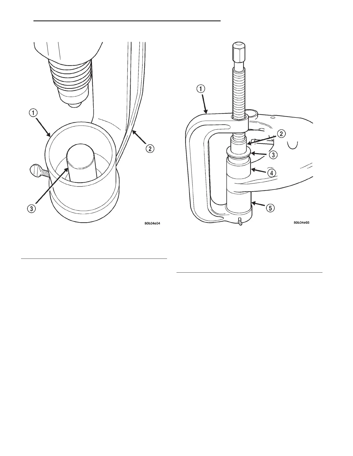
(6) Install Remover/Installer, Special Tool 8173–2,
on end of the threaded push rod on Special Tool
C-4212F.
(7) Place special tools on crossmember and bush-
ing (Fig. 7).
(8) Turn the threaded rod, pushing bushing down
through Special tool 8173–3 and into place in the
crossmember. Continue pushing the bushing until
bottoms against Special Tool 8173–4.
(9) Remove special tools.
(10) Verify the bushing is properly centered in the
crossmember bore and the outer bushing lips are not
pinched.
SPECIFICATIONS
FRAME DIMENSIONS
Frame dimensions are listed in metric scale then
converted to inch scale listed in parenthesis. All
dimensions are from center to center of Principal
Locating Point (PLP), or from center to center of PLP
and fastener location. Vertical dimensions can be
taken from the work surface to the locations indi-
cated (Fig. 8) through (Fig. 11).
Fig. 6 Special Tools
1 – SPECIAL TOOL 8173–1
2 – SPECIAL TOOL C-4212F
3 – SPECIAL TOOL 8173–4
Fig. 7 Bushing Installation
1 – SPECIAL TOOL C-4212F
2 – SPECIAL TOOL 8173–2
3 – BUSHING
4 – SPECIAL TOOL 8173–3
5 – SPECIAL TOOL 8173–1
LH FRAMES AND BUMPERS 13 - 11
DISASSEMBLY AND ASSEMBLY (Continued)