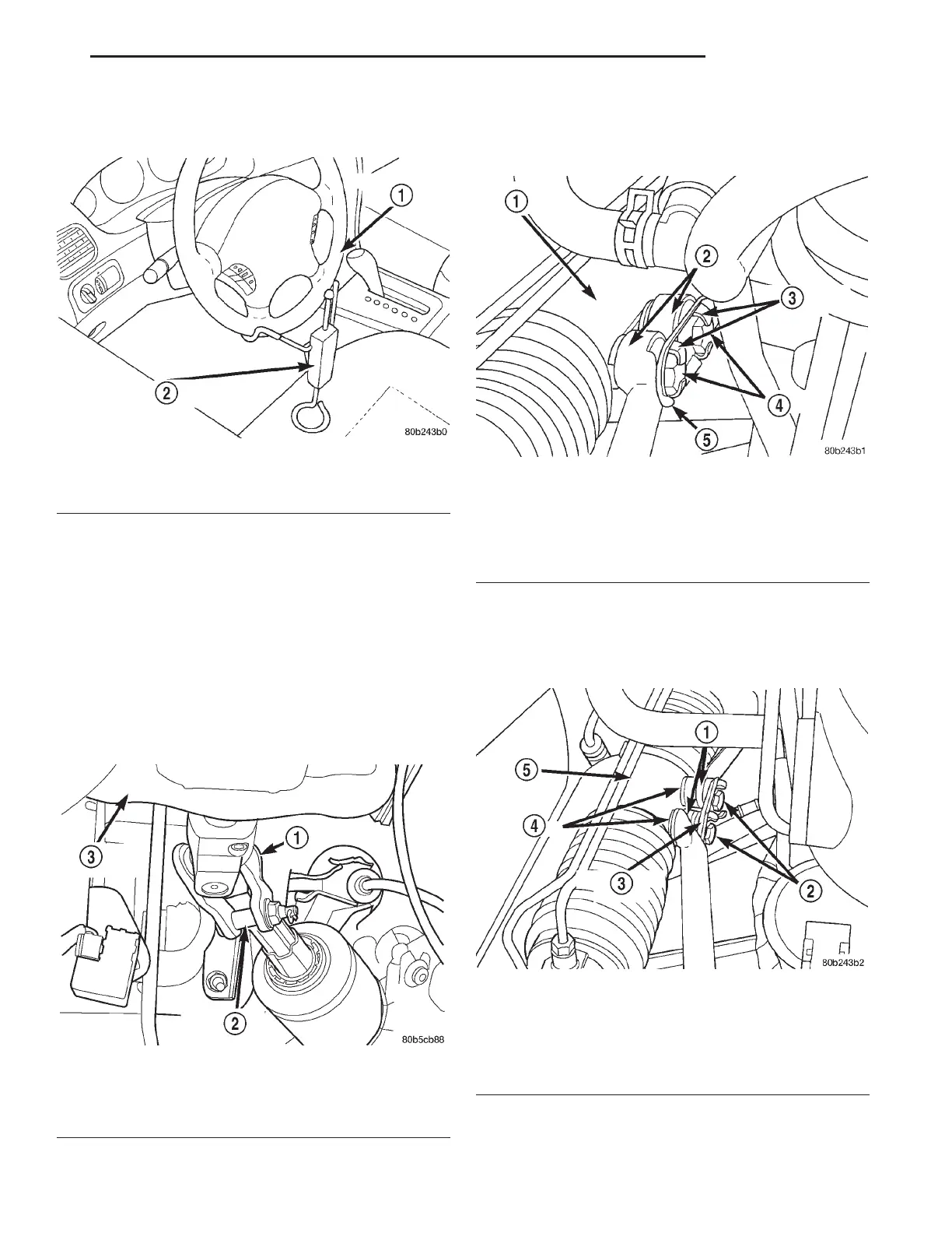
(9) Using a steering wheel clamp, (Fig. 15) lock the
steering wheel from rotating.
CAUTION: Before removing the steering column
coupler from the intermediated steering shaft be
sure the steering wheel is locked from rotating (Fig.
15). If the steering wheel is allowed to rotate freely
after it is disconnected from the intermediated
shaft, the clockspring will be damaged and will
need to be replaced.
(10) Remove the retaining pin and the coupler bolt
from the steering column coupler (Fig. 16). Separate
the intermediate steering shaft from the steering col-
umn coupler.
(11) Bend back the retaining tabs on the mounting
plate for the tie rod to steering gear mounting bolts
(Fig. 17).
(12) Remove the bolts, mounting plate and wash-
ers (Fig. 18) attaching the tie rods to the steering
gear. Lay the tie rods on top of the transaxle bell
housing.
Fig. 15 Steering Wheel Lock Installed (Typical)
1 – STEERING WHEEL
2 – STEERING WHEEL CLAMP
Fig. 16 Steering Column Coupler
1 – COUPLER
2 – PINCH BOLT
3 – STEERING COLUMN
Fig. 17 Tie Rod Attachment Bolt Retaining Tabs
1 – STEERING GEAR
2 – TIE RODS
3 – RETAINING TABS
4 – BOLTS
5 – PLATE
Fig. 18 Tie Rod To Steering Gear Attaching Bolts
1 – TIE RODS
2 – BOLTS
3 – MOUNTING PLATE
4 – WASHERS
5 – STEERING GEAR
LH STEERING 19 - 13
REMOVAL AND INSTALLATION (Continued)