(21) Remove the bolts mounting the power steer-
ing hoses to the left frame rail (Fig. 23).
(22) Raise vehicle.
(23) 300M only — The front fascia will require
removal to access the power steering cooler. See
Frames and Bumpers, Group 13, in this service man-
ual for required procedure.
(24) Remove the power steering fluid return hose
from the power steering fluid cooler (Fig. 24). Let the
remaining power steering fluid drain out of the
return hose and the power steering fluid cooler.
(25) Lower the vehicle.
(26) Remove the power steering fluid hoses from
the vehicle. The power steering fluid hoses are
removable from the back of the engine compartment
(Fig. 25).
INSTALL
(1) Install the power steering hoses into the vehi-
cle using the reverse of the removal procedure
(2) Raise the vehicle.
(3) Install the power steering fluid return hose on
the power steering fluid cooler (Fig. 24). Be sure the
hose clamp is installed past the upset bead on
the power steering fluid cooler.
(4) 300M only — Reinstall front fascia.
(5) Lower the vehicle until the tires are just clear
of the floor
(6) Install the power steering hoses onto the left
frame rail (Fig. 23) by installing the routing clip
bolts. Tighten the bolts to 10 N·m (89 in. lbs.).
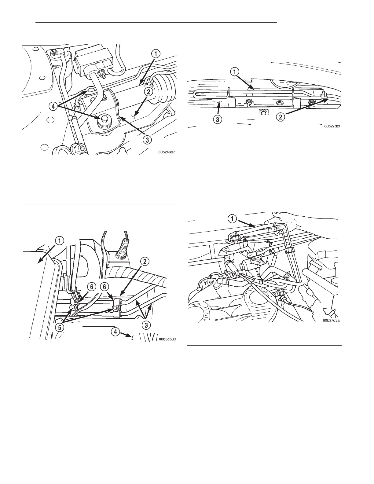
Fig. 22 Steering Gear Attachment To Crossmember
(Right Side)
1 – STEERING GEAR
2 – CROSSMEMBER
3 – MOUNTING BRACKET
4 – MOUNTING BOLTS
Fig. 23 Power Steering Hose To Frame Rail Mounting
1 – COOLANT RECOVERY BOTTLE
2 – FRAME RAIL
3 – POWER STEERING FLUID TUBES
4 – LEFT STRUT TOWER
5 – BOLTS
6 – ROUTING CLIPS
Fig. 24 Power Steering Return Hose At Cooler
1 – POWER STEERING FLUID COOLER
2 – POWER STEERING FLUID RETURN HOSE
3 – AIR CONDITIONING CONDENSER
Fig. 25 Power Steering Hose Removal/Installation
1 – POWER STEERING FLUID HOSES
LH STEERING 19 - 15
REMOVAL AND INSTALLATION (Continued)