INSTALLATION
(1) Install the outer tie rod into the adjustment
sleeve. Do not tighten the adjustment pinch bolt
at this time.
(2) Install the outer tie rod into the steering arm
on front strut. Install tie rod to steering arm attach-
ing nut (Fig. 28). Tighten the attaching nut a torque
of 37 N·m (27 ft. lbs.).
(3) Install the tire and wheel assembly.
(4) Install and tighten the wheel mounting nuts in
proper sequence until all nuts are torqued to half
specification. Then repeat the tightening sequence to
the full specified torque of 129 N·m (95 ft. lbs.).
(5) Lower vehicle.
CAUTION: When setting the front Toe on the vehi-
cle, the maximum dimension of exposed threads
allowed on the adjuster and outer tie rod cannot
exceed the distance shown in (Fig. 30). If the maxi-
mum distance is exceeded, inadequate retention of
either the adjuster or the outer tie rod can result.
This condition can cause separation of the outer tie
rod end from the inner tie rod. Ensure that adjust-
ment sleeve pinch bolts are torqued to the required
specification when Toe setting procedure is com-
pleted.
(6) Check the front wheel toe setting on vehicle
and make required changes. When making front
wheel toe adjustments, be sure the maximum
exposed thread requirements (Fig. 30) are not
exceeded.
CAUTION: When torquing the adjuster pinch bolt,
the following procedure must be followed to ensure
adequate retention of the adjuster is obtained. Not
following this procedure, could result in the Toe
Setting Adjustment changing and/or the separation
of the outer tie rod from the inner tie rod.
(7) After completion of the tie rod end installation
and the toe adjustment procedure, tighten adjuster
pinch bolt (Fig. 30) to a torque of 38 N·m (28 ft. lbs.).
Make sure the outer tie rod maintains correct per-
pendicular orientation while tightening the adjuster
pinch bolt.
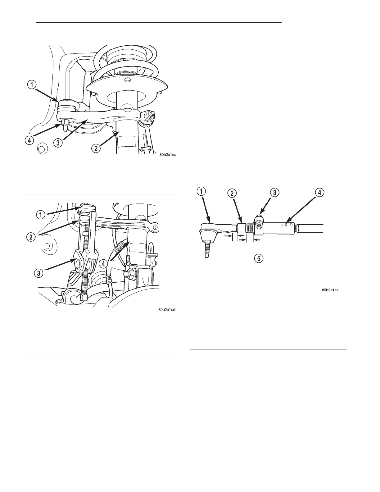
Fig. 28 Tie Rod Nut
1 – OUTER TIE ROD
2 – STRUT
3 – STEERING ARM
4 – NUT
Fig. 29 Tie Rod Removal From Steering Arm
1 – TIE ROD END
2 – STEERING ARM
3 – SPECIAL TOOL
C-3894A
4 – STRUT
Fig. 30 Tie Rod Thread Engagement Requirements
1 – OUTER TIE ROD
2 – ADJUSTER
3 – PINCH BOLT
4 – INNER TIE ROD
5 – ALLOWABLE THREADS EXPOSED ON OUTER TIE ROD
AND ADJUSTER IS A MAXIMUM OF 20 MILLIMETERS.
REFER TO AREA INDICATED ABOVE ON THE OUTER TIE
ROD AND ADJUSTER.
LH STEERING 19 - 39
REMOVAL AND INSTALLATION (Continued)