(3) Remove the lower instrument panel cover. The
lower instrument panel cover is attached by retain-
ing clips along the top and right edge.
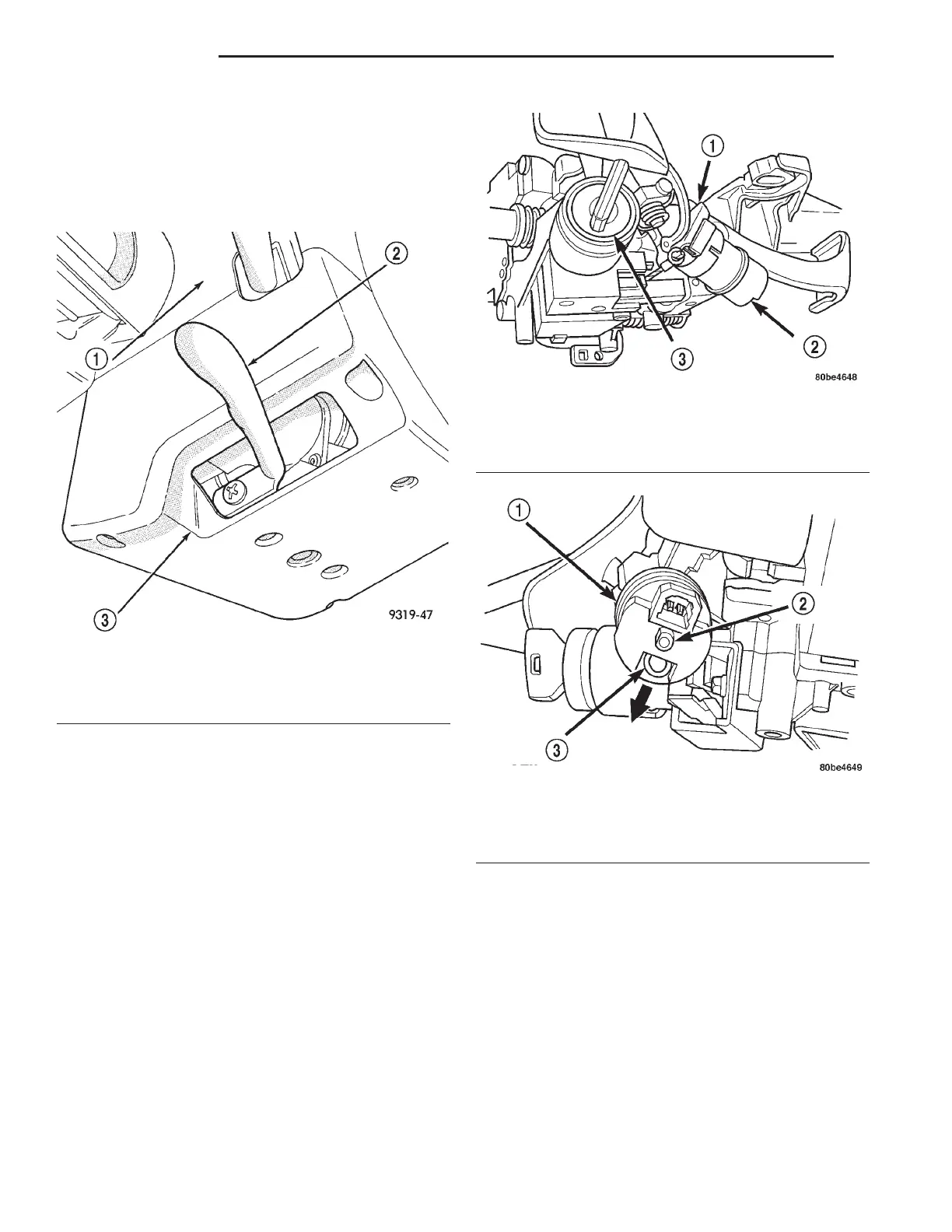
(4) Remove the tilt lever and the upper and lower
steering column shrouds from steering column
assembly (Fig. 35). Then remove center outlet bezel.
(5) Remove the brake transmission shift interlock
(BTSI) solenoid from the shift lever mechanism (Fig.
36). To do so, perform the following:
(a) Disconnect the wiring harness connector
from the solenoid.
(b) Remove the retainer clip from the end of the
solenoid (Fig. 37).
(c) Slide the solenoid straight off the shift lever
mounting stud.
(6) Remove the gear shift cable from the attaching
pin on the shift lever assembly.
(7) Unlock shift cable adjuster.
(8) Remove the 3 Torx head screws attaching the
shift lever assembly to the steering column tilt hous-
ing (Fig. 38), then remove shift lever assembly from
tilt housing and unhook the ignition interlock cable
from shift lever assembly (Fig. 38).
(9) Remove the interlock cassette from the steering
column and discard it.
NOTE: A new interlock cassette must be installed
when a new shift lever assembly is installed.
INSTALLATION
(1) Install new shift lever assembly on tilt housing
of steering column. Install and securely tighten the 3
Torx head screws attaching shift lever assembly to
tilt housing.
(2) Install the gear shift cable onto the cable
attaching pin on shift lever assembly.
(3) Lock the gear shift cable adjuster.
(4) Install the brake transmission interlock sole-
noid on the shift lever mechanism. To do so, perform
the following:
(a) Align the flat inside the solenoid (Fig. 39)
with the flat on the shift lever mounting stud.
(b) Slide the solenoid completely onto the shift
lever mounting stud aligning the plastic guide
Fig. 35 Tilt Lever And Upper And Lower Shrouds
1 – UPPER SHROUD
2 – TILT LEVER
3 – LOWER SHROUD
Fig. 36 BTSI Solenoid
1 – SHIFT LEVER BRACKET
2 – SOLENOID
3 – KEY CYLINDER
Fig. 37 Solenoid Retainer Clip Removal
1 – SOLENOID
2 – MOUNTING STUD
3 – RETAINER CLIP
19 - 58 STEERING LH
REMOVAL AND INSTALLATION (Continued)