STEERING COLUMN SHAFT UPPER COUPLER
REMOVE
(1) Remove steering column assembly from vehicle.
Refer to the Steering Column Removal Section in
this group of the service manual for the required
removal procedure.
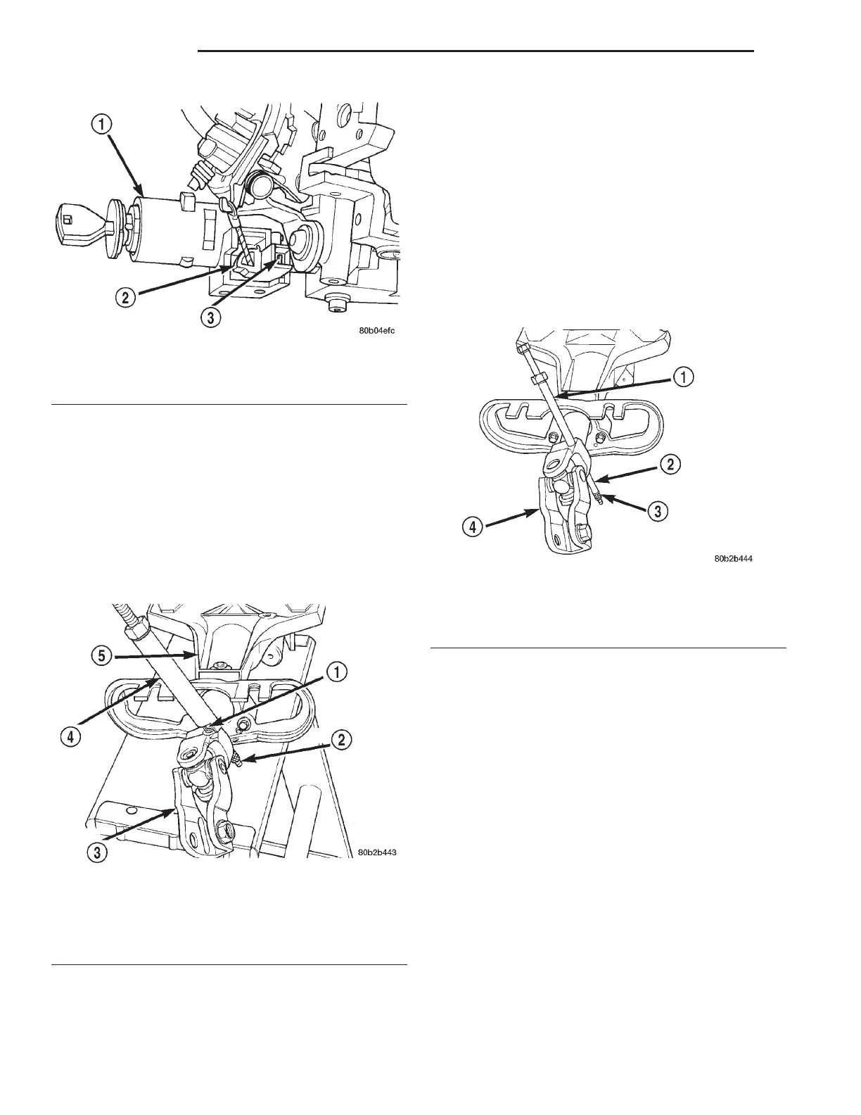
(2) Install Puller, Special Tool 6831-A, through
center of roll pin in flex coupler and install knurled
nut (Fig. 43).
(3) While holding hex on end threaded rod, tighten
the nut on threaded rod of Puller, Special Tool
6831-A. This will pull the roll pin out of the coupler.
(4) Remove the coupler from the steering column
shaft
INSTALL
(1) Start roll pin into coupler prior to installing
coupler on steering column shaft. Install roll pin into
coupler just far enough to square roll pin to hole in
flex coupler. If roll pin is installed too far, coupler
will not slide onto steering column shaft.
(2) Install coupler on steering shaft until correctly
positioned to allow roll pin to be installed in coupler.
(3) Install Puller, Special Tool 6831-A, through
center of roll pin and install knurled nut (Fig. 44).
(4) Using Puller, Special Tool, 6831-A, (Fig. 44)
install roll pin into the coupler until spring pin is
fully installed through both sides of the coupler.
SPECIFICATIONS
STEERING COLUMN FASTENER TORQUE
SPECIFICATIONS
DESCRIPTION TORQUE
Steering Wheel:
Retaining Nut ............ 61N·m(45ft.lbs.)
Speed Control Switch Screws ......... 1.5N·m
(13 in. lbs.)
Airbag Module Mounting Bolts ......... 8N·m
(75 in. lbs.)
Steering Column:
Mounting Nuts .......... 12N·m(105 in. lbs.)
Mounting Bolts .......... 12N·m(105 in. lbs.)
Upper Coupler Pinch Bolt . . 27 N·m (240 in. lbs.)
Fig. 42 Ignition Interlock Adjustment Tab
1 – LOCK CYLINDER HOUSING
2 – INTERLOCK CASSETTE
3 – ADJUSTMENT TAB
Fig. 43 Removing Roll Pin
1 – ROLL PIN
2 – KNURLED NUT
3 – FLEX COUPLER
4 – SPECIAL TOOL 6831–A
5 – STEERING COLUMN
Fig. 44 Tool Set-Up For Installing Roll Pin
1 – SPECIAL TOOL 6831–A
2 – ROLL PIN
3 – KNURLED NUT
4 – FLEX COUPLER
19 - 60 STEERING LH
REMOVAL AND INSTALLATION (Continued)