GRILLE - LOWER - 300M
REMOVAL
(1) Open hood.
(2) Remove fascia.
(3) Remove two screws attaching foam.
(4) Remove lower grille eight attaching clips.
(5) Remove grille.
INSTALLATION
(1) Place grille into position on vehicle.
(2) Install eight attaching grille clips.
(3) Install two screws attaching foam.
(4) Install fascia.
(5) Check alignment of the grille.
EXTERIOR BADGEING ATTACHED WITH
DOUBLE SIDED FOAM TAPE
REMOVAL
(1) Mark reference points before removing.
(2) Using a heat gun gently apply heat in a circu-
lar motion to loosen the adhesive bond.
(3) Using a nonmetallic prying device, such as a
plastic or wood trim stick gently pry up at corners
and remove.
(4) Clean off all traces of adhesive or double sided
tape from the panel with a general purpose adhesive
remover.
INSTALLATION
(1) Clean panel surface with isopropy alcohol.
(2) Align badgeing to reference points.
(3) Install and press securely to full adhesive con-
tact
(4) Clean away any reference points.
EXTERIOR BADGEING/TAPE STRIPES
ATTACHED WITH ADHESIVES
REMOVAL
(1) Mark reference points before removing.
(2) Using a heat gun gently apply heat in a circu-
lar motion to loosen the adhesive bond.
(3) With your fingernail lift up and peel away
badgeing/tape from panel, using a heat gun as you
go.
(4) Clean off all traces of adhesive from the pan-
el(s) with a general purpose adhesive remover.
INSTALLATION
(1) Clean panel surface with isopropy alcohol.
(2) Remove paper carrier and align badgeing/tape
to reference points or adjacent panel.
(3) Install and press securely, using a plastic
spreader to eliminate all air bubbles.
(4) Remove top protective carrier.
(5) Clean away any reference points.
WHEELHOUSE SPLASH SHIELD – FRONT
REMOVAL
(1) Hoist and support vehicle on safety stands.
(2) Remove front wheel.
(3) Remove strut assembly from vehicle. Refer to
Group 2, Suspension.
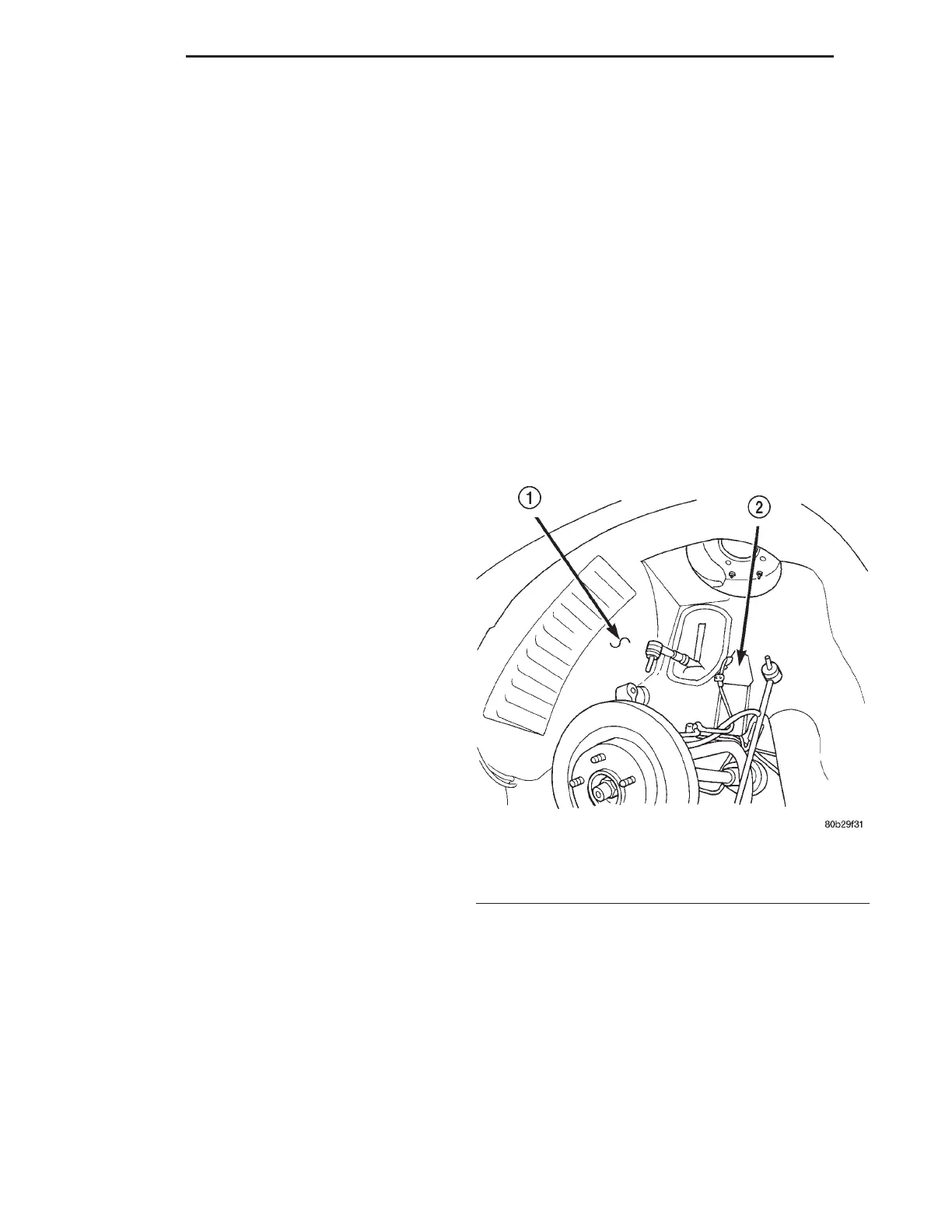
(4) Remove screws attaching speed sensor bracket
(Fig. 27). Move bracket to access speed sensor wire
connector.
(5) Disconnect speed sensor wire connector.
(6) Remove fasteners attaching splash shield to
inner wheelhouse.
(7) Remove splash shield from vehicle.
INSTALLATION
(1) Place splash shield into position.
(2) Install fasteners to attach splash shield.
(3) Connect speed sensor wire connector.
(4) Install screws attaching speed sensor bracket.
(5) Install strut assemble
(6) Install front wheel.
(7) Lower vehicle.
Fig. 27 Wheelhouse Splash Shield
1 – SPLASH SHIELD
2 – SPEED SENSOR BRACKET
23 - 42 BODY LH
REMOVAL AND INSTALLATION (Continued)