REMOVAL
(1) Remove intake manifold plenum and intake
manifold. Refer to the Engine section.
(2) For the 2.7 L engine remove the right cylinder
head. Refer to the Engine section.
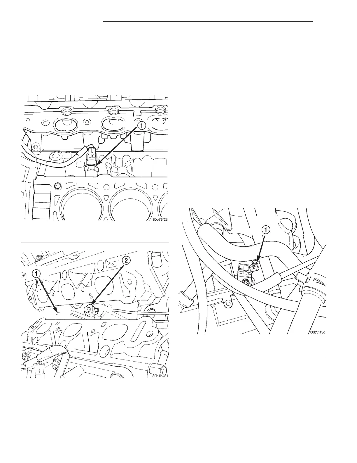
(3) Disconnect electrical connector from knock sen-
sor(s) (Fig. 18) or (Fig. 19).
(4) Use a crows foot socket to remove the knock
sensor bolt.
INSTALLATION
(1) Install knock sensor. Tighten bolt to 10 N·m (7
ft. lbs.) torque. Over or under tightening affects
knock sensor performance, possibly causing
improper spark control.
(2) Attach electrical connector to knock sensor.
(3) Install the cylinder head. Refer to the Engine
section.
(4) Install intake manifold plenum and intake
manifold. Refer to the Engine section.
COIL CAPACITOR
REMOVAL
(1) Remove the negative battery cable.
(2) Disconnect the electrical connector (Fig. 21) or
(Fig. 20).
(3) Remove nut and capacitor.
INSTALLATION
(1) Install capacitor and tighten nut.
(2) Attach electrical connector to capacitor.
(3) Install the negative battery cable.
IGNITION SWITCH
The ignition switch attaches to the lock cylinder
housing on the end opposite the lock cylinder (Fig.
22). For ignition switch terminal and circuit identifi-
cation, refer to the Wiring Diagrams section.
REMOVAL
(1) Disconnect negative cable from battery.
(2) Remove tilt lever attaching screw. Remove
lever.
Fig. 18 Knock Sensor 2.7 L
1 – KNOCK SENSOR
Fig. 19 Knock Sensor 3.2/3.5 L
1 – CYLINDER BLOCK
2 – KNOCK SENSOR
Fig. 20 Ignition Coil Capacitor
1 – IGNITION COIL CAPACITOR
8D - 8 IGNITION SYSTEM LH
REMOVAL AND INSTALLATION (Continued)