REMOVAL
(1) Disconnect negative cable from battery.
(2) Remove the tilt lever attaching screw. Remove
lever.
(3) Remove the upper and lower covers from the
steering column.
(4) Turn the ignition key to the run position. When
ignition switch is in the run position, the lock cylin-
der retaining tab will depress.
(5) Depress tab and slide lock cylinder out of hous-
ing (Fig. 26).
INSTALLATION
(1) Install key in lock cylinder. Turn key to run
position (retaining tab on lock cylinder can be
depressed).
(2) The shaft at the end of the lock cylinder aligns
with the socket in the end of the housing. To align
the socket with the lock cylinder, ensure the socket is
in the Run position (Fig. 27).
(3) Align the lock cylinder with the grooves in the
housing. Slide the lock cylinder into the housing
until the tab sticks through the opening in the hous-
ing (Fig. 28).
(4) Turn key to Off position. Remove key.
(5) If the vehicle has column shift and a new lock
cylinder was used, install and adjust a new interlock
cassette. Refer to Ignition Interlock in this section. If
the vehicle has a floor shift, adjust the interlock
cable when the lock cylinder is replaced. Refer to the
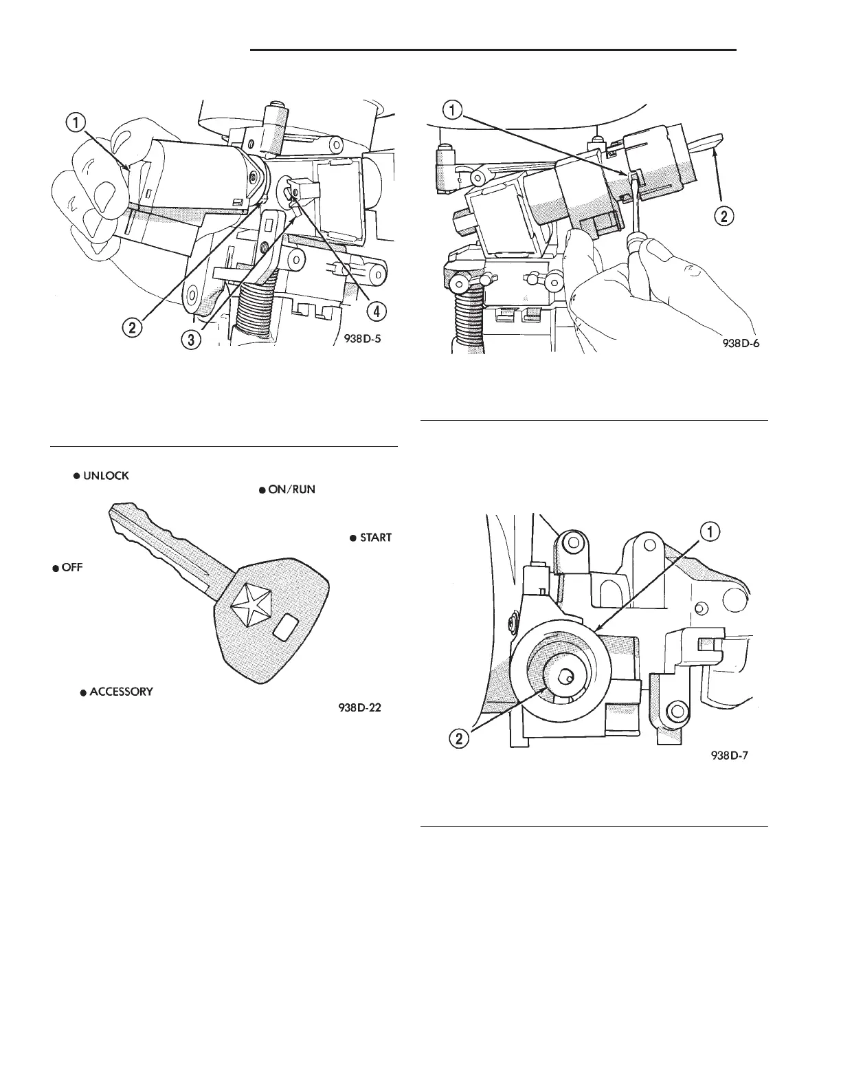
Fig. 24 Ignition Switch Alignment
1 – IGNITION SWITCH
2–TAB
3 – NOTCH
4 – SHAFT
Fig. 25 Ignition Lock Cylinder Detentes
Fig. 26 Lock Cylinder Removal
1–TAB
2 – KEY IN RUN POSITION
Fig. 27 Socket in Lock Cylinder Housing
1 – LOCK CYLINDER HOUSING
2 – SOCKET IN RUN POSITION
8D - 10 IGNITION SYSTEM LH
REMOVAL AND INSTALLATION (Continued)