tioned between the marks on the cover (Fig. 77) at
both sprocket.
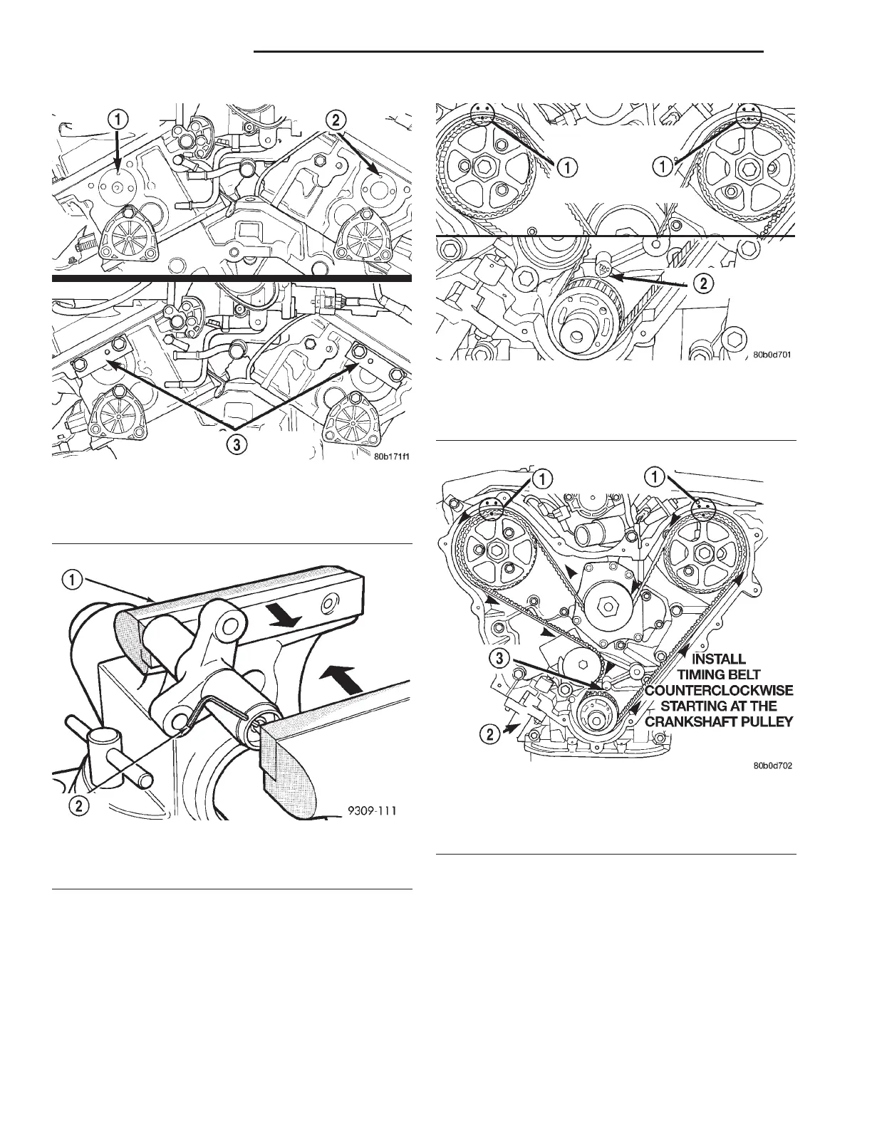
(6) Install the timing belt starting at the crank-
shaft sprocket going in a counterclockwise direction
(Fig. 78). Install the belt around the last sprocket.
Maintain tension on the belt as it is positioned
around the tensioner pulley. Each camshaft sprockets
mark should still fall between the cover marks.
(7) Holding the tensioner pulley against the belt,
install the tensioner into the housing and tighten to
28 N·m (250 in. lbs.).
(8) When tensioner is in place pull retaining pin to
allow the tensioner to extend to the pulley bracket.
(9) With number 1 piston at TDC (Fig. 79), hold
the camshaft sprocket hex with a 36 mm (1 7/16 in.)
wrench and tighten the camshaft bolts to 102 N·m
(75 ft. lbs.) plus a 90 degree turn for the Right side
and 115 N·m (85 ft. lbs.) plus a 90 degree turn for
the Left side.
Fig. 75 Camshaft Alignment Special Tools 6642
1 – LEFT CAMSHAFT PILOT HOLE
2 – RIGHT CAMSHAFT PILOT HOLE
3 – CAMSHAFT ALIGNMENT SPECIAL TOOLS 6642
Fig. 76 Compressing Timing Belt Tensioner
1 – VISE
2 – LOCKING PIN
Fig. 77 Camshaft Sprocket Timing Marks
1 – ALIGN CAMSHAFT SPROCKET TIMING MARK BETWEEN
MARKS ON REAR TIMING BELT COVER
2 – CRANKSHAFT AT TDC
Fig. 78 Timing Belt—Installation
1 – ALIGN CAMSHAFTS WITH TIMING MARKS
2 – INSTALL TENSIONER LOOSE
3 – CRANKSHAFT AT TDC
9 - 118 3.2/3.5L ENGINE LH
REMOVAL AND INSTALLATION (Continued)