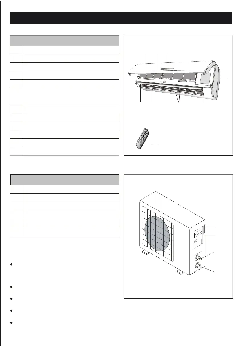
NAMES OF THE PARTS
No.
Description
1
2
Front panel
Air lter
Optional lter (if installed)
3
Terminal block cover
4
Emergency button
5
6
LED Display
Remote control signal receiver
7
Airow direction aps
8
Air deectors
9
Remote control
10
Note: the above gures are only intended to be a
simple diagram of the appliance and may not
correspond to the appearance of the units that
have been purchased.
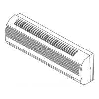
No.
Description
13
Air outlet grille
Electrical box cover
14
gas valve
15
liquid valve
16
11
Indoor unit rating label
17
Outdoor unit rating label
HI-WALL AIR-CONDITIONER
The conditioner is made up of two or more units
connected between themselves through copper
pipes (properly insulated) and an electrical con-
necting cable.
The indoor unit is installed on the walls of the
room to be conditioned.
The outdoor unit is installed on the oor, roof, or on
the wall on suitable brackets.
Technical data of the air conditioner are printed on
the labels placed on the indoor and outdoor units.
The remote control has been designed for easy
and fast use.
12
Ionizer (if installed) generator
13
15
16
17
INDOOR UNIT
3
OUTDOOR UNIT
1
2-3
6
4-5
9
11
8
10
7
14
DIS
PL
AY HE
AL
TH
Y
3D
O
N/O
F
F
SWING
FA
N
TI
MER
SUPE
R
SLEE P MO
DE
ECO
CL
OCK
12