9
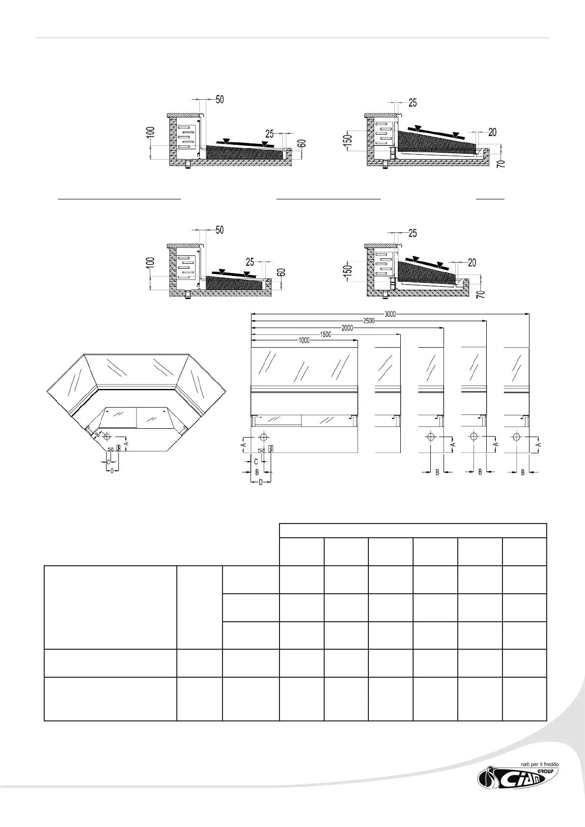
2.4 PIPING POSITION AND ELECTRIC CONTROL BOARD
MODELS
100 150 200 250 300 Ap90
Drain condensation outlet *
number 1 1 2 2 2 1
A (mm) 160 160 160 160 160 160
B (mm) 120 120 120 120 120 120
Refrigerating piping ** C (mm) 90 90 90 90 90 50
Electric power supply *** D (mm) 200 200 200 200 200 150
All the plate sections are reported in the following gure. The part highlighted with a dark line represents the area
in which the refrigerated product has to be placed.
SERIES 900
SERIES 750
STATIC AIRED
CLIENT SIDE
OPERATOR SIDE
 Loading...