10
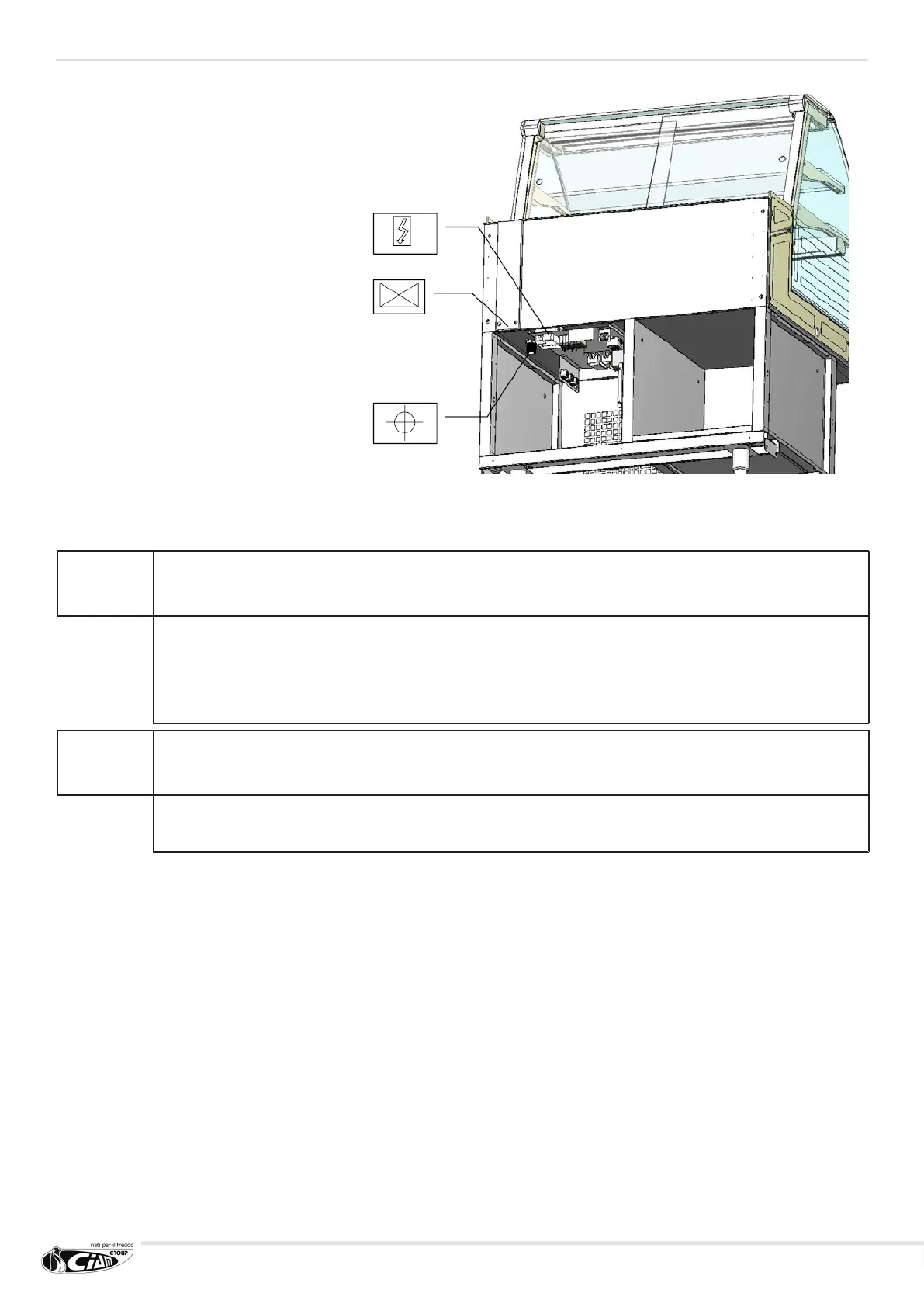
* The drain (or drains) condensing
outlet position is indicated in the
drawings. Such drain is in PVC
with one inch threading; already
connected to a corrugated 75cm
long exible pipe with male terminal
with 32mm connection.
** The point in which the two
refrigerated plant pipes come
out of the plate is indicated in the
drawings (external diameter ø10mm
for suction and ø6mm for liquids).
In case the motor is not supplied
or supplied disconnected, the pipes
extend for about a meter inside the
equipment compartment underneath
the terminal board, always in
correspondence of the indicated
point.
*** The point of the terminal board in
which the spider box is positioned
and to which the general power
supply of the same board arrives is
indicated in the drawings; already
connected three pole cable about
1.5m long with plug socket.
!
WARNING
DO NOT CONFUSE THE OUTLET DIAMETERS OF THE REFRIGERATING PLANT PIPES (10MM FOR
SUCTION AND 6MM FOR LIQUIDS) WITH THE DIMENSIONS OF THE PIPES WHICH NEED TO BE
EXTENDED IN CASE OF INTERNAL CONDENSING UNIT.
IN SUCH CASE, THE PIPING SECTIONS WILL DEPEND UPON THE REQUESTED POWER, THE UNIT
POSITION, ENVIRONMENTAL CONDITIONS, ETC.
IMPORTANT NOTE
IN CASE OF EXTERNAL CONDENSING UNIT, IT IS RECOMMENDED TO CONTACT THE CIAM TECHNICAL
DEPARTMENT TO CORRECTLY PROPORTION THE ENTIRE PLANT.
 Loading...