VECTIOS
POWER TM
PJ EN-8
6 - TRANSPORT AND HANDLING
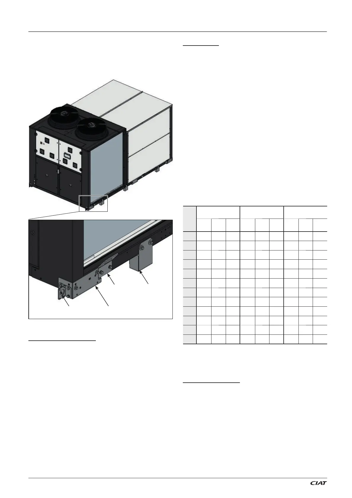
Forklift truck
The unit is designed to be transported safely by using a forklift
truck. The transport supports make it easy to insert the forks.
These forks must come in on the side of the unit, ensuring that
the centre of gravity of the unit remains within the forks, because
a misbalance in the transport may cause the unit to turn over
and fall from the forklift truck.
Note: the module with the rotary heat exchanger (CW assembly)
includes two guides in its base frame to accommodate the forks.
The recommended length for the forks will be bigger than the
unit width (refer to the following table), so that the entire weight-
bearing structure of the unit can be supported on the forklift truck.
The standards and recommendations of the forklift truck must
also be respected with regards to the maximum load, inclination
of the fork carriage, elevation of the load for transport, and, in
particular, the maximum speed.
The transport elements must be removed before starting the
installation of the unit. They are secured to the unit by means
of Allen M10 screws.
IPJ
C0, CS
assemblies
CP, CR, CW
assemblies
CQ, CT
assemblies
Length
(mm)
Width
(mm)
Height
(mm)
Length
(mm)
Width
(mm)
Height
(mm)
Length
(mm)
Width
(mm)
Height
(mm)
0420
3820 2257 2293 3820 2257 2555 3825 2268 2555
0450
3820 2257 2293 3820 2257 2555 3825 2268 2555
0500
3820 2257 2293 3820 2257 2555 3825 2268 2555
0560
4224 2257 2340 4224 2257 2555 4229 2268 2555
0620
4224 2257 2340 4224 2257 2555 4229 2268 2555
0680
4224 2257 2340 4224 2257 2555 4229 2268 2555
0720
4224 2257 2340 4224 2257 2555 4229 2268 2555
0760
5300 2257 2421 5300 2257 2555 5306 2268 2555
0840
5300 2257 2421 5300 2257 2555 5306 2268 2555
0960
5300 2257 2421 5300 2257 2555 5306 2268 2555
1050
6350 2257 2494 6350 2257 2555 6356 2268 2555
1200
6350 2257 2494 6350 2257 2555 6356 2268 2555
Units dimensions for transportation (*):
(*) Consult the overall dimensions of the available assemblies
in paragraph 7.6 “Recommended service clearance”.
Gripping point
Container discharge
In case of container transport, the unit incorporates skids that
facilitate the unloading. This method will be used only when it is
possible to place the transport box (trailer, maritime container,
etc.) at the same height as the unloading platform (for example,
a dock).
To do so, there are two gripping point that have to be used for
the drag of the unit from the box.
After unloading, if a forklift is to be used, the transport supports
(always supplied with the unit) have to be mounted.
The skids must be removed before starting the installation of
the unit. They are secured to the unit by means of Allen M8
screws (hex. key 13).
The unit’s bars are fi tted with the following elements to allow
handling:
● Lifting grips to attach the slings of the crane.
● Transport supports for easier insertion of the forklift truck’s forks.
● Skids in case of transport in a container.
Important: The transport supports are not designed to drag
the unit.
Skid
Transport
support
Lifting
grip
Crane with a rocker arm
A rocker arm, as well as approved slings, both suitable for the
dimensions and weight of the unit, must be used in order to carry
out the work safely. To avoid damaging the casing, use textile
slings with shackles.
Only attach the slings to the lifting grips located on each bar.
In models with 4 or 5 grips an H-shaped rocker must be used,
which has a main beam and two secondary beams that allow
elevation over four or fi ve lifting points.
Raise and set down the unit carefully. Take care not to tilt it by
more than 15°, as this could adversely aff ect its operation.
The centre of gravity is not necessarily in the middle of the unit
and the forces applied to the slings are not always identical.
Please consult the weight and the centre of gravity of each
model stated in paragraph 7.5.
After the placing of the unit, it is recommended to remove the
grips as they can be a hindrance for maintenance. Put the grips
back in case of unit transport. The grips are fi xed to the bars
using M10 screws (hex. key 17).
 Loading...