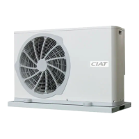
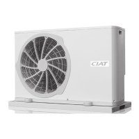
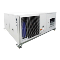
The HCompact2 HA is a series of horizontal package air-to-air heat pumps and cooling units designed for indoor operation. These compact units are equipped with centrifugal fans, air coils, scroll compressors, and electronic control with microprocessors, optimized for R-410A refrigerant. They are suitable for air conditioning applications in medium-power offices, commercial, and industrial spaces where facade aesthetics need to be preserved. The series includes HCompact2 RHA (cooling-only autonomous units) and HCompact2 IHA (reversible heat pump autonomous units). All units are factory-charged with refrigerant and tested to ensure correct operation of all components within their intended operating range. They comply with standards EN 60-204, EN 378-2, and directives Machinery 2006/42 EC, EMC 2004/108/EC, LVD 2006/95 EC, and PED 14/068 EC (Category 2).
Technical Specifications:
The HCompact2 HA series offers cooling capacities from 12.5 to 35.9 kW and heating capacities from 14.2 to 41.0 kW.
- Cooling Conditions (air inlet): Minimum 14 °C WB, Maximum 22 °C WB (indoor coil); Minimum 12 °C (with condensation pressure control down to -10°C), Maximum 48 °C (outdoor coil).
- Heating Conditions (air inlet): Minimum 10 °C, Maximum 27 °C (indoor coil); Minimum -6 °C BH (support element recommended below 5°C WB), Maximum 15 °C WB (outdoor coil).
- Refrigerant: R-410A, with a Global Warming Potential (GWP) of 2088. Charge ranges from 2.5 kg to 6.2 kg, resulting in an environmental impact (t CO2e) from 5.2 to 12.9. Maximum service pressure is 42 bar.
- Electrical Characteristics: 400 V / III ph / 50 Hz (±10%) power supply. Total absorbed current ranges from 21.3 A to 50.8 A, depending on the model.
- Fans: Centrifugal type for both indoor and outdoor circuits. Motor output for outdoor fans ranges from 1.1 kW to 3.0 kW, and for indoor fans from 0.55 kW to 3.0 kW.
- Dimensions (L x W x H): Ranging from 1420 x 1065 x 576 mm (smallest models) to 2300 x 1820 x 824 mm (largest models).
- Weight: From 245 kg to 521 kg.
- Condensate Evacuation: Ø 3/4".
Installation and Usage Features:
- Transport: Units must be handled with care, lifted, and fixed without inclination (max 15°). Forklift transport requires ensuring the center of gravity remains within the forks and that the forks support the entire weight-bearing structure. Skids should not be disposed of until the unit is in its final location.
- Location and Assembling: Units can be installed on the floor or on a brick/steel frame. Damping devices are recommended to avoid noise and vibration transmission. A template of the unit's footprint with anchoring points for silent-blocks is advised for direct silent-block installation. M10 metric threads are provided for silent-block placement. Units can also be fixed to the ceiling using threaded rods and antivibration mounts.
- Air Ducts Connections: Designed for ducted supply and return. Ducts should be calculated based on rated flow and available pressure. Straight duct sections (approx. 1 meter) are recommended after fan discharge. Sharp direction changes should be avoided. Flexible connections are necessary to prevent noise and vibration transmission. Ducts must be made of non-flammable materials that do not emit toxic gases.
- Condensate Drain Connection: All models have two independent condensate drain pans (indoor and outdoor circuits) with asphaltic paint. Female drain joints are bronze, gas thread 3/4". Siphons are mandatory to prevent bad smells and water spills. For correct siphon design in underpressure pans, the "A" height must be at least twice the underpressure.
- Electrical Connections: Requires adherence to electrical wiring diagrams and local norms. Main power supply must match the data plate voltage. All connections must be correct and tight.
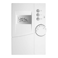
- Electronic Control: AVANT electronic control is standard, comprising a main board and a TCO user terminal. An optional pGD1 maintenance terminal facilitates initial scheduling, parameter modification, and alarm description.
- TCO Thermostat Installation: The thermostat should be fixed at 1.5 m height in an appropriate location, avoiding direct sunlight, outdoor air, or internal heat sources.
- Interchangeable Air Supply/Return: Both indoor and outdoor supply/return panels are interchangeable, allowing on-site configuration according to installation requirements.
- Pulley and Belt Adjustment: Pulleys must be on the same plane, checked with a ruler or laser aligner. Belt tension is adjusted by tightening the tensor screw and must be re-checked after 24 hours of motor operation.
Safety Features:
- Low Pressure Pressostat: Stops operation if pressure drops below 2 bar (disconnects at 2 bar, resets automatically).
- High Pressure Pressostat: Stops operation if pressure reaches the setpoint (disconnects at 42 bar, reactivates automatically).
- Magnetothermals: Located at the beginning of power lines for compressor and motorfan protection.
- Automatic Switch in Control Circuit: Protects against continuous surges and short circuits.
- Main Door Switch: Mechanical device preventing access to the electric panel when the unit is energized.
- Safeties at the Compressor: Non-return valve built-in and temperature probe for discharge protection (stops unit if discharge temperature exceeds 135°C).
- Anti-fire Safety (with return probe option): Electronic control can activate a safety anti-fire stop if return air temperature exceeds 60°C. The unit will not restart until the temperature drops below 40°C.
- Air Flow Control (optional): Differential pressostat measures air supply flow, detecting fan belt breakages. Compulsory for units with electrical heaters.
- Clogged Filter Detector (optional): Differential pressostat indicates when filters need maintenance.
Maintenance Features:
- General Recommendations: Do not lean on the unit or copper refrigerant tubes. Keep the unit and surrounding area clean. Perform visual and auditory inspections. Conduct corrosion control on metallic parts. Check insulation foam and electrical connections.
- Air Coil: Check for dust and grease. Clean with a vacuum cleaner (perpendicular to fins) or low-pressure water cleaner. Degreaser can be used for grease.
- Condensate Drain Pans: Ensure pans are clean and free of stagnant water. Check that drains are not clogged. Clean with water and non-abrasive detergent.
- Centrifugal Fan: Verify clean turbine and motor. Keep a spare belt set for fans. Motors and fans have sealed, lubricated bushings.
- Compressor: For replacement, disconnect power, empty refrigerant, electrically disconnect, unscrew piping, remove fixings, place new compressor, check oil charge, tighten screws (11 Nm for models 55, 65, 80; 15 Nm for models 90, 120, 160), screw piping, make vacuum, and reload gas.
- Dehydrant Filter: Preserves cooling circuit cleanliness, removes humidity, and neutralizes acids. Check dirt by measuring temperature difference at inlet and outlet. Replace if necessary.
- Oil: Use protection creams when handling. Store and handle with precaution. Discard "disposable" rags appropriately. Check oil level and aspect; replace if color changes or contamination is present.
- Refrigerant: Periodic tightness control (Regulation CE N° 517/2014) by qualified personnel. Frequency depends on global warming potential (t CO2e): < 5 t CO2e (not subjected), 5 to 50 t CO2e (every year), 50 to 500 t CO2e (every 6 months), > 500 t CO2e (every 3 months). Frequency is halved if a leakage detection system is installed. Take precautions during partial opening of the circuit to minimize refrigerant loss. Store excess refrigerant in appropriate containers.
- Servomotor (optional): Check state in units with condensation pressure regulation damper.
- Air Filters: Clean gravimetric filters with a vacuum cleaner or by submerging in water. Creased opacimetric filters must be replaced.