Do you have a question about the CIAT AQUALIS 2 Series and is the answer not in the manual?
Overview, unpacking, and identification of the Aqualis 2 unit.
Warranty service and critical safety parameters for installation and operation.
Statement confirming compliance with European directives.
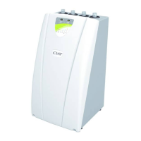
Guidelines for selecting the optimal location for the control terminal.
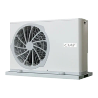
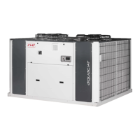
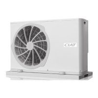
Points to check before handling, placing, or connecting the outdoor heat pump unit.
Information on unit weights and crucial handling precautions.
Technical drawings and dimensions for different Aqualis 2 models.
Details on pipe connection diameters and water flow rates for different models.
Instructions and recommendations for installing the water filter.
Guidelines for installing pipes and hoses, emphasizing vibration reduction.
Requirements for installing a safety valve, especially with optional electric heaters.
Precautions for condensate water drainage in heating mode, especially in freezing conditions.
Strategies to minimize noise transmission through solid materials and careful unit placement.
Schematic diagrams for cooling-only and reversible models.
Advice on protecting the system from freezing using glycol and corrosion inhibitors.
How glycol concentration impacts system performance factors.
Compliance and general guidelines for electrical connections.
Diagrams and notes for wiring before system startup.
Pre-startup checks including refrigerant leaks, water flow, and electrical connections.
Step-by-step guide for starting the unit and setting initial parameters.
Procedure for bleeding air from the system for optimal performance.
Importance and procedure for bleeding air from the differential water pressure switch.
General advice on disconnecting power before maintenance and specific component checks.
Table for recording operational data for monitoring and troubleshooting.
Introduction to the unit's control components: terminal, electronic board, PSU boards.
Detailed explanation of the terminal unit's screen elements and indicators.
Explanation of the symbols and indicators shown on the terminal display.
How to use the dial to select modes and adjust settings.
Procedure for accessing customer and installer settings via the terminal.
Configuration of cooling, heating, and frost protection modes using P3.
Setting P6 to define auxiliary units and bypass types.
Operating limits for electrical auxiliary units.
Guidelines for using a boiler as a backup heating source.
Using control inputs for remote ON/OFF, frost protection, and mode activation.
Detailed description of the control board components and terminal block locations.
Details on external fan operation in cooling and heating modes.
Operation of the reversing valve in reversible models.
Conditions for powering the condensate drain pan heater cable.
Information on circulator operation, seizure protection, and turn-off conditions.
Overview of automatic restart, short-cycle protection, self-regulating control, and low-noise operation.
Details on swimming pool, humidity, DHW heating, and heat trace cable options.
Distinction between temporary and permanent faults and their impact.
Table listing fault codes, descriptions, types, and possible causes.
Procedure for acknowledging detected faults on the terminal.
Sensor resistance tables and compressor operating limits charts.
Detailed technical data for all Aqualis 2 models.
Schematics of the hydraulic module for cooling-only and reversible models.