36
Français
English
DeutschItaliano
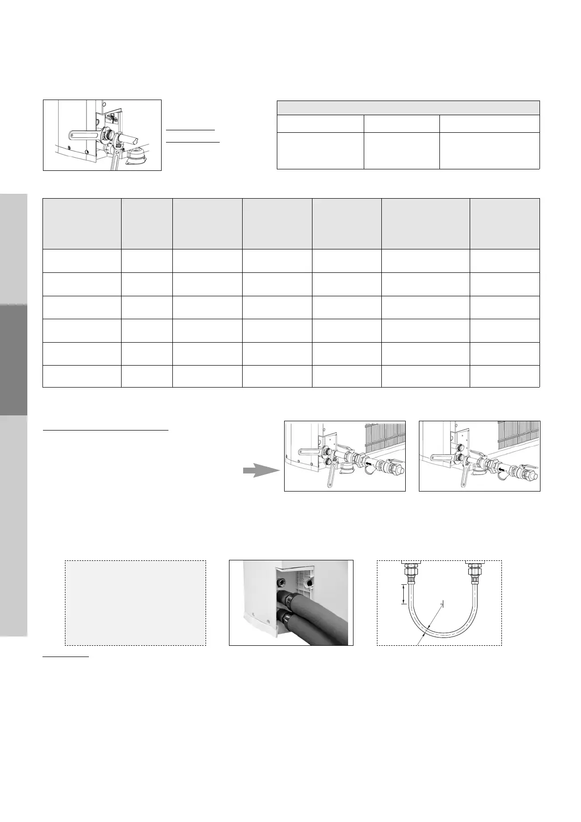
2-2-1 Pipe connections
2-2-2 Installing the filter
2.2 Hydraulic connections
In order to meet the operating conditions
(flow rates, pressure losses)
, a sizing calculation must be performed.
The diameters of the tubes are not necessarily the same as those of the unit.
Suppl
y pipe
connections:
Use two spanners
to tighten the couplings
Diameters of water connections
MODEL
20 / 28 / 35 50 / 65 / 75
dias. of water
connections
(male, gas)
1
1
1
/
4
”
Water flow rates and connections
Minimum diameters calculated for a water connection for your machine 15 m away from its connection to the system.
Filter installation 쒁 mandatory
Install in the direction of flow.
Insulate the filter or install it indoors
(protect from
freezing temperatures).
Connect the kit and filter to the return water line.
Filter mesh: 600 µm maximum
The pipes and tubes should not transmit any forces. Hoses must be used to connect the water pipes to limit as far as possi-
ble the amount of vibrations transmitted to the building. They are obligatory if the unit is installed on anti-vibration
mounts
Insulate the pipes and hoses carefully to prevent heat loss and condensation.
Precautions
: bend the hoses at sufficiently wide angles to avoid pinching the inner tube and restricting the flow of water.
If your system is fitted with an optional electric heater a 4 bar safety valve must be placed on the water loop. It must
be installed near the heater without a shut-off valve between the two.
Important: to protect against damage and injury, keep all shut-off valves open and cut off the valve on the heating
equipment (Aqualis 2, electric heater, boiler, domestic hot-water tank) when the equipment is in use.
Always comply with the
appropriate bend radius.
R min. > 6 x dia.
L min. < 6 x dia.
Hoses:
1”: R 140 mm
1
1
/
4
”: R 172 mm
2-2-3 Installing the hoses
2-2-4 Safety valve
Aqualis 2
Minimum
flow rate
(m
3
/ h)
Nominal flow
rate
(m
3
/h)
During cold water
production
Nominal flow
rate
(m
3
/h)
During hot water
production
Hydraulic
connection
Copper
tube
Hydraulic
connection
Steel tube
Hydraulic
connection
PE tube
(polythene)
20
0.7 0.9 1
28 x 1 DN26 26 x 34 DN25 1”
32 x 2.9
28
0.9 1.2 1.4
28 x 1 DN26 26 x 34 DN25 1”
32 x 2.9
35
1.1 1.46 1.72
32 x 1 DN30 33 x 42 DN32 1 1/4”
32 x 2.9
50
1.5 1.98 2.27
36 x 1 DN34 40 x 49 DN40 1 1/2”
40 x 3.7
65
2 2.7 2.8
38 x 1 DN36 40 x 49 DN40 1 1/2”
40 x 3.7
75
2.45 3.04 3.5
42 x 1 DN40 40 x 49 DN40 1 1/2”
50 x 4.6
Cooling only models Reversible models

 Loading...