33
2.
INSTALLATION
2.1 Location of the control terminal and the heat pump
2-1-1 Location of the control terminal
On delivery, the control terminal can be found inside the machine, near the electrical box (open top to access it).
Specifications
- Settings stored in memory for two hours following a power cut
- Blue backlit digital display
- Maximum dimensions: 128 x 85 x 31 mm
- Wall mounting plate
- Protection rating: IP 30
- Operating temperature limits: -15°C to +50°C
- Power supply: 12 V DC +/- 0.5 V
- Maximum consumption: 25 mA
- Class II insulation
Installation
Selecting a location
In most cases, the control terminal should be placed in the room in which the atmosphere is to be controlled.
The terminal also works as a room thermostat and thus plays an active role in controlling the unit.
However, special applications (e.g. industrial, process) may require water temperature control. If so, the terminal may be located
anywhere without affecting control (see paragraph under table on page 21).
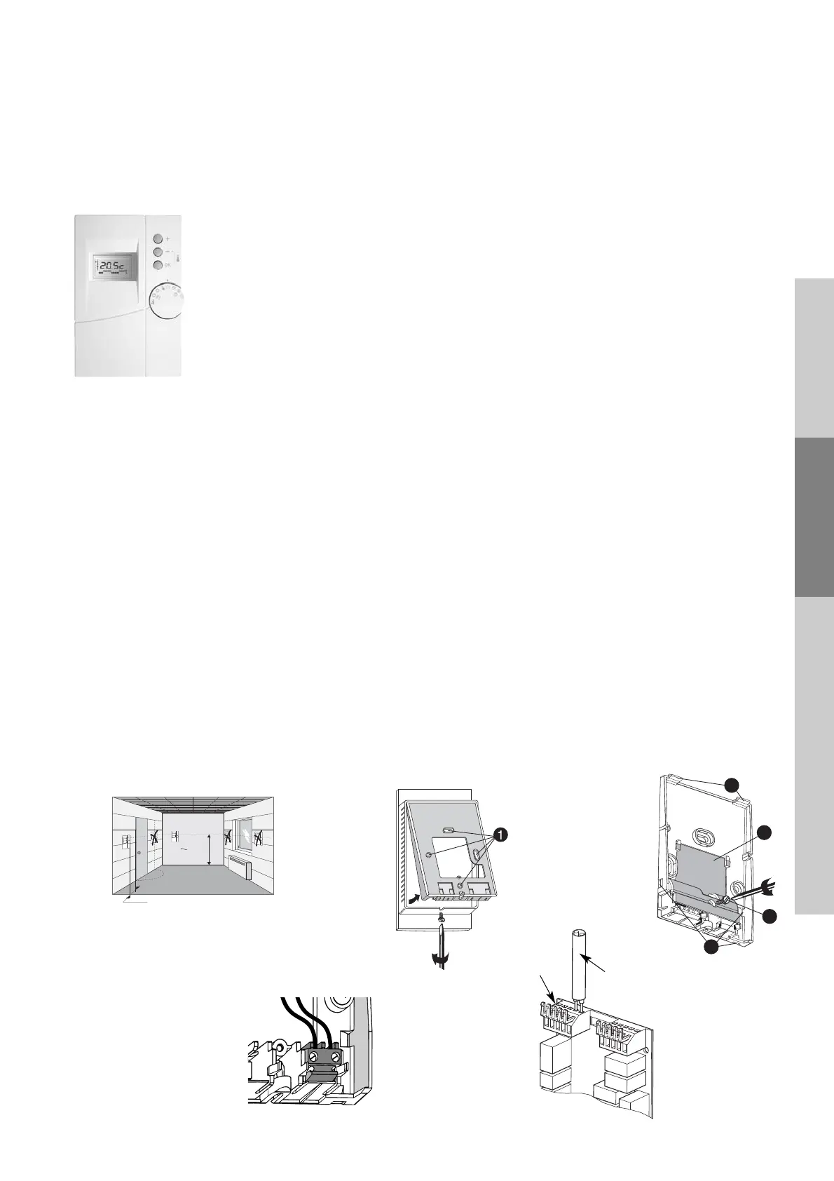
Location in room
The terminal should be installed at a recommended height of 1.5 m and at an accessible location away from sources of heat
(e.g. chimney, sunlight) and draughts (windows, doors) (Fig. 1)
Mounting
First detach the terminal from its mounting plate, as shown in Fig. 2).
Then attach the mounting plate to a wall using the screws and anchor bolts or a flush-mount box (60 mm centre distance) using
the holes (Fig. 2).
To do so, loosen the screw (Fig. 3) and remove the terminal block cover .
If necessary, remove the knockouts (Fig. 3) to route through the connection cable.
Connection
- Attach the two wires to the terminal (Fig. 4).
- Replace the terminal cover and fasten it in place with the screw (Fig. 3).
- Place the thermostat on its mounting plate. To do so, first insert the tabs (Fig. 3) then push down on the thermostat until it
snaps into place.
- Connect the two wires between the thermostat and the control board on terminal block J2 on the unit’s control board
(Fig. 5).
- Cable length < 50 m maximum — cable cross-section: AWG 16 to 28;
or 0.2 mm
2
<S<1.5 mm
2
.

 Loading...