HEAT PUMPS - AIR CONDITIONING - REFRIGERATION - AIR HANDLING - HEAT EXCHANGE - NA 12.65 D
8
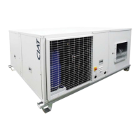
Horizontal package air conditionners
HCompact2 HA
V-220004
V-220005
Electronic control
• AVANT electronic control
All HCompact2 HA units have an AVANT electronic control as
standard from the factory comprised of a main board and a TCO
user terminal.
Optionally, this control can have a terminal for pGD1 maintenance
that facilitates the initial scheduling of the unit, the modifi cation of the
operating parameters and the description of the alarms produced.
Note: For more detailed information on this control please refer to
the specifi c brochure.
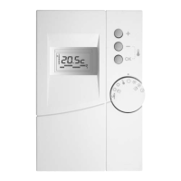
Recommendations for the TCO thermostat installation
From the thermostat some of the unit operation aspects are
controlled: operation modes, setpoint, differential, timings...
Because of this, it is very important to chose an appropriate location
within the room since in it is where the unit’s control probe is located.
This probe must report about the environmental conditions of the
occupied area.
The thermostat must be fi xed at a height of 1.5 m y all possible
interferences must be avoided: sun, outdoor air, internal heat
sources... Mount the thermostat to the wall using the bracket, do not
leave it hanging from the wire or embedding it in the wall.
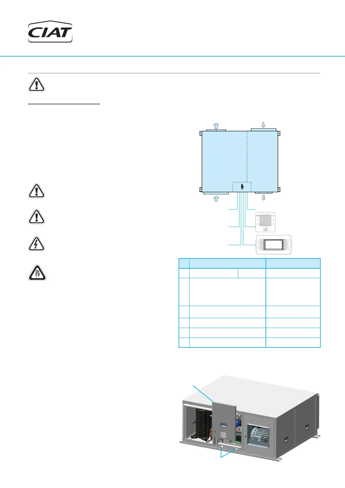
Electric
panel
Power supply inputs
8. CHECKING BEFORE COMMISSIONING
Electrical Connections
Note: Under no circumstance should the unit be started without having read the brochure completely.
Installation norms
To have electrical power to the unit: wire intake, conductor section and
their calculations, protections, etc..., ask the information provided in this
document (refer to technical characteristic table), the electrical scheme
included with the unit and norms in effect that regulate the installation
of air conditioning units and electrical receivers.
Verify that electrical power supply corresponds to the one on the data
plate and that the voltage remains constant according to the stipulated
range.
Check that the electrical connections are correct and tight
(an electrical diagram is included with each unit, along with
its legend).
Note: All connections in the site are the responsibility of the
installer. These connections are always made as per the
current regulation.
To prevent electrical shocks, make all electrical connections
before energizing the unit. Check that the automatic switch
is closed. Omitting this can cause personal damage. Make
the ground connection before any other electrical connection.
The installer must fi x line protection elements according to
the effective legislation.
Connection chart
1
2
3
4
5
6
Outdoor
air circuit
Indoor
air circuit
pGD1
TCO user
terminal
maintenance
terminal (opt.)
No. Description 55 to 160
1
Main power supply 400 III (±5%) 3 + GND
2
TCO user terminal connection
2 wires for power supply
230V + 1 shielded cable
for communication type
AGW20 / 22 (1 braided pair
+ drainwire + shielding)
3
pGD1 maintenance terminal
connection (optional)
telephone cable 6 wires
standard (RJ12 connector)
4
Remote off/on (optional) 2 wires
5
Main alarm signal (optional) 2 wires
6
Safety electrical heaters (optional) 2 wires
The same power supply used for powering the control board must
also be used for powering the terminal.