Plus 42 - 45 - 50 - 55
09-2008
4
3 - 95005 - DANGER, PARTS IN MOTION. BEFORE REMOVING PROTECTION GUARDS, STOP
THE TRACTOR, REMOVE THE KEY FROM THE TRACTOR’S CONTROL PANEL AND
ENSURE THAT ALL MOVING PARTS HAVE STOPPED
- Positioned on the fan casing next to the outflow vent.
4 - 95015 - BEFORE UTILISING THE RELEASE DEVICE, STOP THE TRACTOR, REMOVE THE KEY
FROM THE TRACTOR’S CONTROL PANEL AND ENSURE THAT THE FAN HAS
STOPPED
- Positioned in the forward part of the machine, on the mobile protection cover of the
access to the release device.
5 -95010 - MAXIMUM OPERATING SPEED OF THE DRIVE OUTLET (PTO): 540 RPM
- Positioned on the forward part of the machine, on the lower part of the tank and close
to the drive outlet.
6 - 95007 - DANGER OF SPRAYS: KEEP AT A SAFE DISTANCE
- Positioned on the upper part of the fan casing.
7 - 95006 - WARNING: CONSULT THE USER AND MAINTENANCE MANUAL BEFORE USING OR
INTERVENING ON THE MACHINE
Positioned on the right hand side of the tank, in the forward part of the machine.
8 - 95009 - DANGER: GLOVES MUST BE USED TO EMPTY THE TANK
- Positioned on the right hand side and lower part of the tank, near the discharge lever
tap.
9 - 95012 - DANGER: MOUNT THE WHEELS AFTER HAVING HITCHED THE MACHINE TO THE
HOISTER AND DISMANTLE THEM BEFORE UNHITCHING THE MACHINE FROM THE
HOISTER
- Positioned on the right hand side and lower part of the tank.
Use and maintenance
10 - 95059 - HOOKING POINT FOR THE LIFTING OF THE MACHINE
- Positioned on the frame, above the fan’s casing.
11 - 95079 - CHECK THE OIL LEVEL EVERY 8 HOURS: FAN SHAFT BEARINGS
- Positioned on the chassis, over the fan casing.
12 - 95054 - GREASE EVERY 200 HOURS: FAN TIGHTENER SUPPORT AND FREEWHEEL
- Positioned on the chassis, in the low, rear side, on the left.
- Positioned in the front section, on the tank, in a low position near the Power Takeoff.
13 - 95081 - INDICATION OF THE WHEELS OPERATING PRESSURE (ACCESSORY)
- Positioned on the wheel (accessory).
14 - 95057 - HAND WASHING TANK TAP
- Positioned on the right-hand side of the tank, next to the tap.
15 - 95065 - WARNING: NEVER OPERATE THE SPRAYER WITHOUT LIQUID IN THE TANK
- Positioned on the forward part of the tank, above the gauge.
16 - 95058 - INDICATION ON THE OPERATION OF THE 3-WAY TAP (P5)
- Positioned on the 3-way tap.
17 - 95084 - INDICATION ON THE OPERATION OF THE RINSING TAP (P16)
- Positioned on the right side, under the tank (For models on which it is forseen)
09-2008
Plus 42 - 45 - 50 - 55
65
00001
Marrone
F1
Valve 1
Valve 2
12 V
GRN
Black 1.5
Red 1.5
10A
1
Switch
2
Switch
DL1
1
1
2
2
M M
Bianco
Giallo
Arancio
+
-
Nero 1.5
Red 1.5
Pressure
regulator
1
2
M
Nero
Rosso
F2
10A
P
GRN
HL1
Red
Green
Pressure
transducer
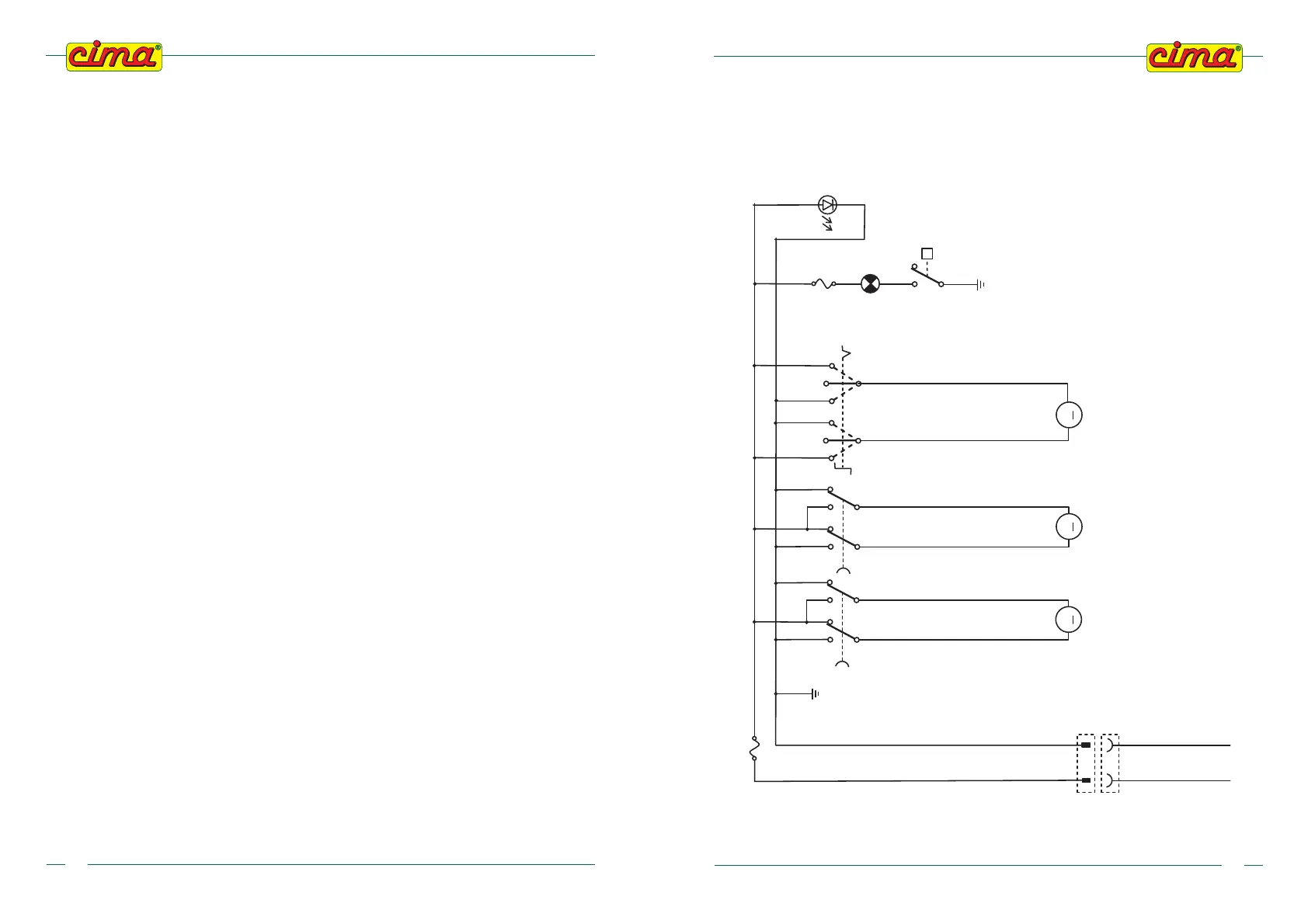
16.2 - WIRING DIAGRAM
(for versions where it is foreseen)