Plus 42 - 45 - 50 - 55
09-2008
32
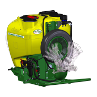
6.1 - POSITIONING OF FAN CASING
The fan’s air outlet must be positioned according to the distribution device to be mounted and the modality
in which it is to be utilised. The operation is possible since the fan’s casing can be rotated on its axis
up to 360°.
POSITIONING OF THE CASING:
1. Position the sprayer on the ground if it is mounted on the tractor.
Switch off the tractor and remove the key from the control panel.
2. By undoing the locking nut, loosen the collar which supports and locks the casing to the frame,
located opposite the suction grill.
3. Rotate the casing and place the outlet in the position necessary for assembling (indications
contained in the use and maintenance booklet of the distribution device).
4. After this has been done fasten the collar again.
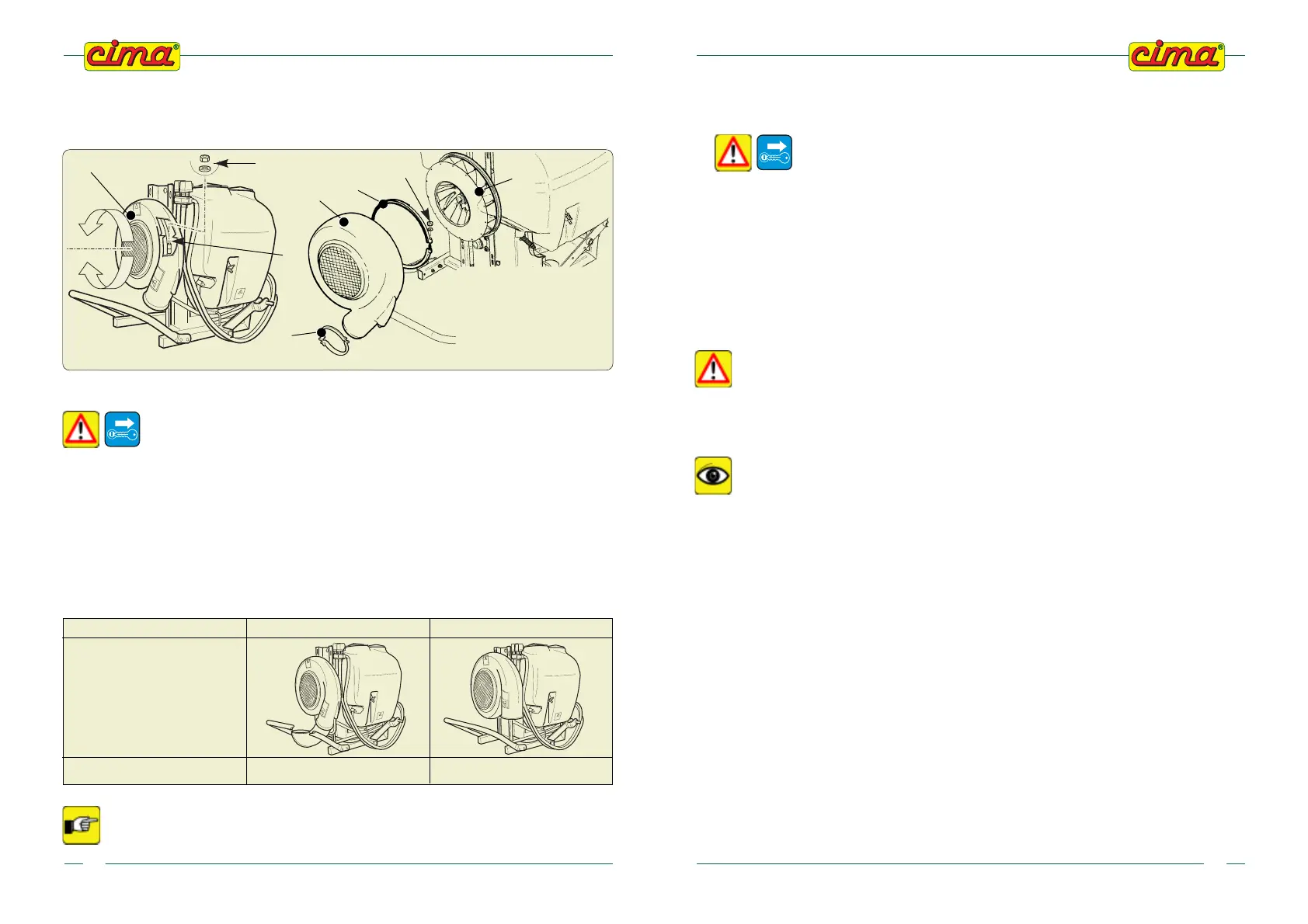
6.2 - ELBOW FITTINGS OF DISTRIBUTION DEVICES
The elbow fittings support and connect the distribution devices to the fan casing. Several types are assembled
on available standard machines, while others,must be supplied together with the distribution device.
In the “Distribution Heads - Operation and maintenance instruction” the type of
elbow necessary for the connection is specified together with the assembling
instructions.
PLUS SERIES 42 - 45 - 50 55 - 55S - 55E
SPRAYER PROVIDED WITH 180° ELBOW WITHOUT ELBOW
STANDARD
BASIC
MODELS
00144
00145 00187
5
3
4
2
00980
2
5
1
4
LEGEND
1. ELBOW LOCKING COLLAR
2. FAN CASING
3. FAN
4. NUT
5. FAN CASING
LOCKING COLLAR
09-2008
Plus 42 - 45 - 50 - 55
37
8.1.b Fan engagement to perform the treatment
EXECUTION:
1. Disengage the power take off (PTO) and rest the machine on the ground.
2.
Stop the tractor, remove the key from the control panel and check that
the fan is stopped.
3. Undo the mobile protection cap’s fixing screw and rotate it so as to access the disengagement
tunnel.
4. Fully press the spring push button, push the front body forward, if necessary, turning it to the right
or left, until the frontal teeth of the joint engage the corresponding teeth of the pulley; at the same
time, the spring push button must return to the outward position. This way, the body is again
integrated with the pulley, thus transmitting the movement to the fan.
5. Reposition the mobile protection cover and suitably tighten the securing screw.
6. Start the tractor and lift the sprayer to position the universal joint shaft.
8.2 - FILLING THROUGH POURING FROM THE TOP
For this type of filling, use the supplementary filler (BS) located in the upper right-
hand side of the tank, towards the front of the sprayer (opposite the filler of the
hand washing tank).
THE INLET OF THE FILLER PIPING MUST NEVER COME INTO CONTACT WITH THE ANTI-
PARASITIC MIXTURE: IT MUST ALWAYS BE KEPT AT A SAFE HEIGHT ABOVE THE TANK
FILLER AND MUST BE EQUIPPED WITH A NON-RETURN VALVE.
THE PUMP MUST NEVER RUN DRY
EXECUTION:
1. Disengage the fan (for the version where foreseen): see point 8.1.a.
2. Close the taps of the 2-way distributor:
a. if manual (P9), set the levers in the horizontal position;
b. if electrical, position the latch switches (E10).on “OFF”
3. Check that the following cocks
- P2 (o P15): is open (lever on "a");
- P6: is on working position (lever on “a”);
- P12 (for the version where foreseen): closed cock (lever on “c”).
- P6, pressure regulator: is completely open for the unit’s first use, or on the already selected
position for the outstanding treatment or for the previous one.
4. Pour water in the tank to about 1/3 capacity through the supplementary filler BS.
5a. FILLING WITH POWDER PRODUCTS BY UTILISING THE MIXER (for which is foreseen)
5a1.Pour the dose of powder into the cup-like filter through the main filler (BP).
5a2.Close the tank’s main filler (BP).
5a3.Open the tap (P12) (lever on “a”).
5a4.Set the lever of tap (P6) to the “b” position.
5a5.Engage the Power Takeoff and set it up to a running rate of at least 500 RPM.
5a6.Complete the filling with water and close the lid of the secondary filler (BS).
5a7.Close the cock (P12) (lever on “c”).
5a8. Put the thee-way faucet (P6) in work position (the lever on “a”).