09-2008
Plus 42 - 45 - 50 - 55
25
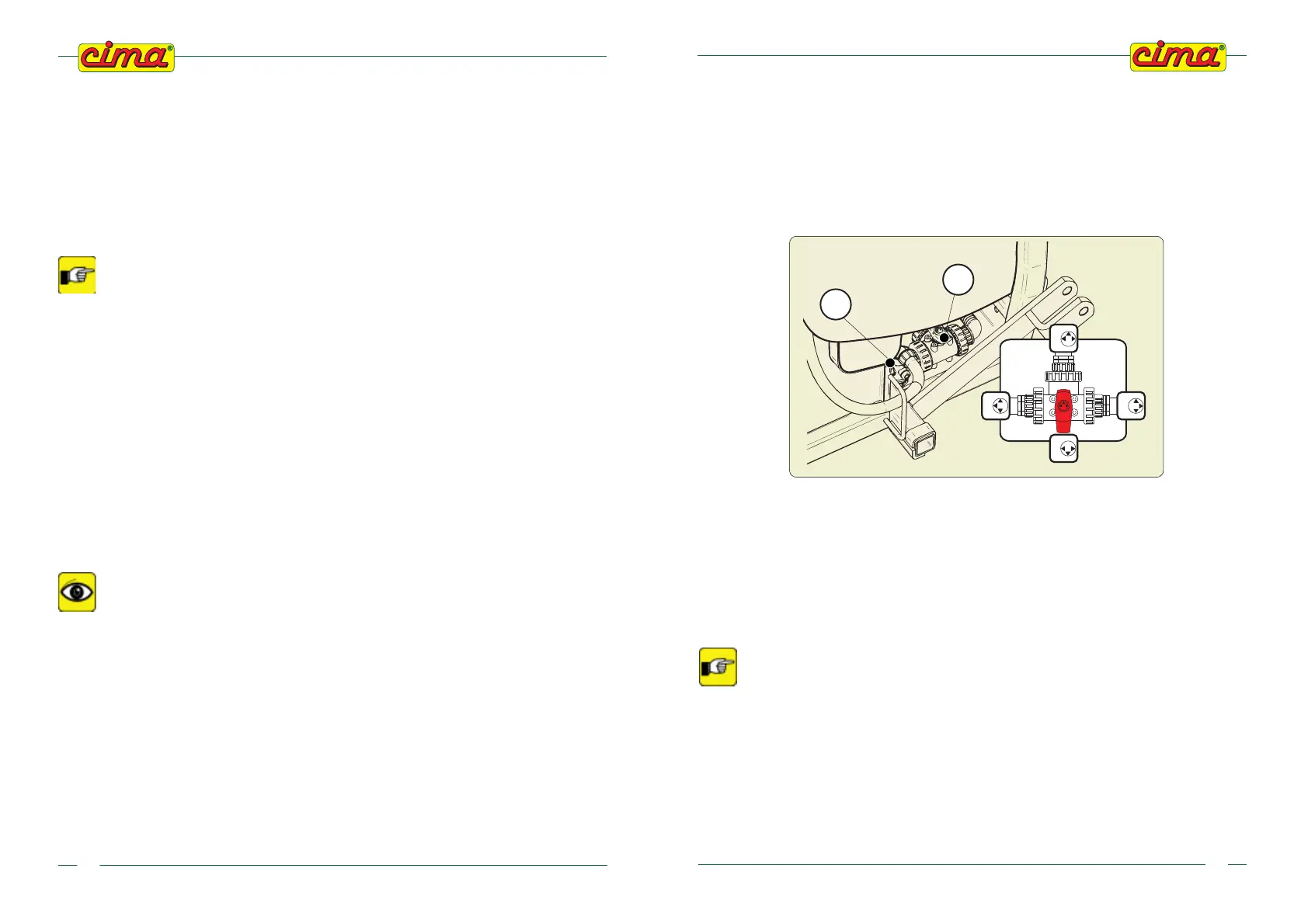
P15 - 3-WAY PLANT-WASHING TAP (For the models on which it is foreseen)
The cock (P15) is joined to the tank (P1) and, on one side, to the plant-washing tank (P17) through pipe
(T7), on the other side it is joined to the centrifugal pump (P4) through the suction pipe (T1).
The unit-washing circuit allows to wash the hydraulic circuit (with the exclusion of the tank), in every
moment and independently on the tank load conditions, i.e., also with the mixture present inside the
tank. When the tap (P15) is placed to position “b”the clean water for the unit washing is taken from
the unit-washing tank (P17) by simultaneously excluding the suction from the main tank.
The 3-way cock lever can be positioned as here following specified:
a – TREATMENT (WORK)
The liquid gets out from the tank (P1) and is sucked by the pump (P4); this is the NORMAL operating
position, which is used in order to carry out the treatment and/or to keep the mixing on. The connection
with washing tank is closed.
b – WASHING PROCESS
The fluid gets out from the unit-washing tank (P17) and is sucked by the pump (P4); that is the position
which is used, in order to carry out the hydraulic circuit WASHING.
TO AVOID THE RETURN OF CLEAN WATER TO THE TANK, WITH CONSEQUENT DILUTION
OF THE MIXTURE CONTAINED IN IT, CLOSE THE FAUCET (P3) AND COMPLETELY CLOSE
THE REGULATOR by rotating the manual regulator handle (P5) clockwise or by
turning the pressure up (keep the joystick on “+” for about 15 seconds for the
versions with pressure regulation electrovalve), DURING THE WASHING.
c – EMPTYING OF THE TANK
In this position, the tank (P1) is emptied. The union with the centrifugal pump is closed. In order
to empty the tank, the drain plug of the union tee (P16) must be removed.
d – COMPLETE DRAINAGE
In this position, it is possible to empty: the tank (P1), the pump (P4) and all the pipes of the hydraulic
circuit. If the plant-washing tank is also filled, it is emptied too.
P16
P15
d
b
a
c
00680
00680
Plus 42 - 45 - 50 - 55
09-2008
44
g. Keep to the preliminary operations already indicated (10.1.c), in case of wind conditions prevailing.
h. Stop the engine, remove the key from the tractor’s control panel and lower the hoist during
stoppages.
i. Pay particular attention to the treatment when close to boundaries and in proximity of dwellings,
waterways, roads or public-usage paths.
10.4 - PROCEDURE TO WASH THE HYDRAULIC CIRCUIT
(head-pump)
In case of machines equipped with unit-washing tank, every time it is necessary
to suspend the treatment, it is possible to carry out the hydraulic circuit washing
process, independently on the loading conditions, i.e., also when the tank is still
containing some product mixture, so avoiding any possible clogging and assuring
the perfect efficiency of the machine when the treatment is carried on again.
In case of prolonged idle periods, it is recommended to keep the mixture agitated
(see Chapter 9).
In order to carry out the hydraulic circuit washing process, follow the instructions here specified:
a. Close the faucet (P3) of exclusion of the additional agitation.
b. Close the pressure regulator completely, by rotating the hand regulator (P5) handle clockwise or
by turning the pressure up (keep the joystick on “+” for about 15 seconds) for the E.P.A. versions.
c. Open the cock (P15), by setting it to position “b”; in that way the clean water contained inside the
unit-washing tank is sucked by the pump (P4) and gets into the hydraulic circuit.
d. Engage the PTO and take it to the correct distribution condition (540 rev/min - see paragraph 4.4.2)
CAUTION: THE PUMP MUST NEVER RUN DRY
e. Aprire i rubinetti del distributore manuale (P9) (o le elettrovalvole E9 portando su ON gli interruttori
sulla centralina elettrica di comando E10); far funzionare l’atomizzatore, irrorando sull’appezza-
mento ancora da trattare, per un tempo sufficiente a verificare la fuoriuscita di acqua pulita dalla
testata di distribuzione.
That easy procedure allows to eliminate every fuel mixture residual from all the
hydraulic circuit components, so assuring in first place the accurate cleaning and the
consequent efficiency of the calibrated holes of the rotary disc regulators.
f. Disengage the PTO.
g. Close the cock (P15) by taking it to the A-WORK position
h. Open the faucet (P3) of exclusion of the additional agitation.