Do you have a question about the CIMCO 21 Series and is the answer not in the manual?
Overview of the instrument's physical layout and status indicator lights.
Instructions for using display controls and operating buttons.
Procedures for system testing and fan mode control.
Defines fail-safe start-up and mentions available options.
Details on input power connection and fan power control.
Instructions for connecting temperature sensors and system ground.
Information on trip and alarm relay configurations.
Overview of status indicators and display control functions.
Details on system test controls and test mode sequence.
Description of operation controls and fan mode settings.
Table outlining step mode functions and their descriptions.
Initial start-up status and instructions for checking the instrument fuse.
How to display maximum temperature memory (MTM) and other phases.
Procedure to reset all maximum temperature memories to zero.
Instructions for fan mode operation and silencing local alarms.
General description of system test and sequence for test modes.
Detailed sequential actions during system test mode.
Overview of standard default settings and custom programming.
The Cimco Series 21 is a microprocessor-controlled instrument designed for monitoring and controlling temperature in industrial applications, particularly those involving transformers. It provides comprehensive temperature management, including fan control, alarm functions, and trip mechanisms, to ensure the safe and efficient operation of connected equipment. The device features a user-friendly interface with a face-plate for displaying operational status, temperature readings, and control options.
The primary function of the Series 21 is to monitor temperature inputs from multiple phases using non-magnetic Type E thermocouples. It automatically identifies and displays the highest temperature among the monitored phases, ensuring that critical hot spots are always visible. The instrument incorporates a Maximum Temperature Memory (MTM) feature, which records and retains the highest temperature reached since the last reset, even through power loss. This is crucial for historical analysis and understanding peak operating conditions.
Beyond monitoring, the Series 21 provides active control over cooling systems, specifically fans. It offers both automatic and manual fan control modes. In automatic mode, the fans are energized based on predefined temperature set-points, ensuring efficient cooling only when necessary. The manual mode allows for continuous fan operation, which can be useful for testing or specific operational requirements. A programmable fan exerciser feature ensures that fans are periodically activated (once per week) to prevent seizing and ensure readiness.
The device also integrates robust alarm and trip functionalities. An alarm is triggered when temperatures exceed a set threshold, providing an early warning of potential issues. The alarm relay is fail-safe, meaning it reverts to an "on-state" if power is lost or a thermocouple is open, ensuring that a warning is always issued in critical situations. A local alarm can be silenced, but the remote alarm relay remains active until the alarm condition clears. The trip function provides a higher level of protection, initiating a shutdown or other critical action if temperatures reach dangerous levels. The trip relay is not fail-safe and only activates with an input signal.
The Series 21 includes a comprehensive system test mode, allowing users to verify the functionality of all relays, LEDs, and set-points. This diagnostic feature steps through various operational states, displaying instrument ambient temperature, fan set-points, alarm set-points, and trip set-points, and confirming the activation and deactivation of associated relays and LEDs. This ensures that all safety and control mechanisms are working correctly.
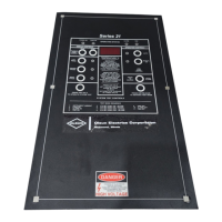
The Series 21 is designed for ease of use with a clear face-plate layout. The "OPERATING STATUS" section provides immediate visual feedback through LEDs for Power On (green), Fans On (amber/yellow), Alarm On (red), and Trip On (red).
The "DISPLAY CONTROL" section allows users to interact with temperature readings. The instrument automatically displays the phase with the highest temperature. Users can press dedicated phase buttons (Left, Center, Right) to view the current temperature of each individual phase. The "MAXIMUM TEMP. MEMORY" buttons (READ and RESET) enable viewing and clearing of the MTM. Pressing "READ" displays the highest temperature recorded, while "RESET" clears this memory. An advanced feature allows users to press and hold the "READ" button and then select a phase button to view the maximum temperature memories of other phases. Additionally, pressing and holding the Left, Center, and Right phase buttons simultaneously displays the mathematical average of the three input temperatures.
The "OPERATION CONTROL" section manages fan operation and alarm silencing. The "FAN MODE CONTROL" offers "AUTO" and "MANUAL ON" options, with LEDs indicating the current mode. Users can press "MANUAL ON" to energize fans continuously or "AUTO" to return to automatic control. The "PRESS TO SILENCE LOCAL ALARM" button allows for temporary silencing of the audible alarm, while the remote alarm relay remains active until the condition is resolved.
The "SYSTEM TEST CONTROLS" are accessed by pressing and holding the bottom left button ("PRESS AND HOLD TO OPERATE SYSTEM TEST") and then pressing and releasing the bottom right button ("PRESS AND RELEASE TO ADVANCE TEST MODE"). This initiates a step-by-step diagnostic sequence, as detailed in the manual's "TEST MODE SEQUENCE" and "TABLE 1." Each step displays a specific parameter (e.g., instrument ambient, fan set-point, alarm set-point) and verifies the corresponding relay and LED functionality.
Input power connection is straightforward, requiring connection to T-11 and T-12, with a 0.25 amp fuse protecting against incorrect voltage application. Fan power control utilizes two outputs (T-1/T-2 and T-3/T-4), each rated for 30 amps, 1 HP at 120 VAC, or 2 HP at 240 VAC. The total rating for both circuits is 30 amps, 2 HP at 120 VAC, or 4 HP at 240 VAC, protected by a 20 amp fuse (maximum 30 amps).
Temperature sensors (Type E thermocouples) are connected to terminal blocks, with specific instructions for lead polarity (red lead is always negative), stripping insulation, and firm clamping. The instrument ground is isolated from the system ground and connects to T-10. Trip and alarm relays are Form C, dry contacts, with the alarm relay being fail-safe and the trip relay not fail-safe.
The Series 21 is designed for robust operation with minimal routine maintenance. The fail-safe design of the alarm and fan contacts ensures that critical safety functions remain active even in the event of power loss or thermocouple failure. This reduces the risk of undetected issues.
The system test mode serves as a powerful diagnostic tool for maintenance. By stepping through the test sequence, technicians can quickly verify the functionality of all internal components, including temperature displays, LEDs, and relays. This allows for proactive identification of potential issues before they lead to operational failures. The ability to silence local alarms during testing or troubleshooting prevents unnecessary noise while allowing remote alarms to remain active for safety.
The fan exerciser feature, which energizes fans once per week, contributes to preventive maintenance by ensuring that the cooling system remains operational and prevents fan motors from seizing due to inactivity.
In cases where the instrument does not respond to commands, a software reset procedure (pressing and holding buttons 1, 6, and 9 simultaneously) can restore the device to its normal start-up mode, effectively resolving minor software glitches without requiring a complete power cycle or more extensive troubleshooting.
The manual also provides guidance on checking the instrument fuse if the "Power on" status light is off, indicating a potential power supply issue that can be easily addressed. For any programmable features or special default settings, users are advised to contact Cimco Electronics, ensuring that any modifications are made with proper authorization and expertise. This approach minimizes the risk of incorrect configurations that could impact the device's performance or safety.
| Screen Size | 21.5 inches |
|---|---|
| Aspect Ratio | 16:9 |
| Refresh Rate | 60 Hz |
| Resolution | 1920 x 1080 |
| Response Time | 5ms |
| Brightness | 250 cd/m² |
| Contrast Ratio | 1000:1 |
| Viewing Angle | 178° (H) / 178° (V) |
| Input Ports | HDMI, VGA |
| Power Consumption | 25W |