Layout and function
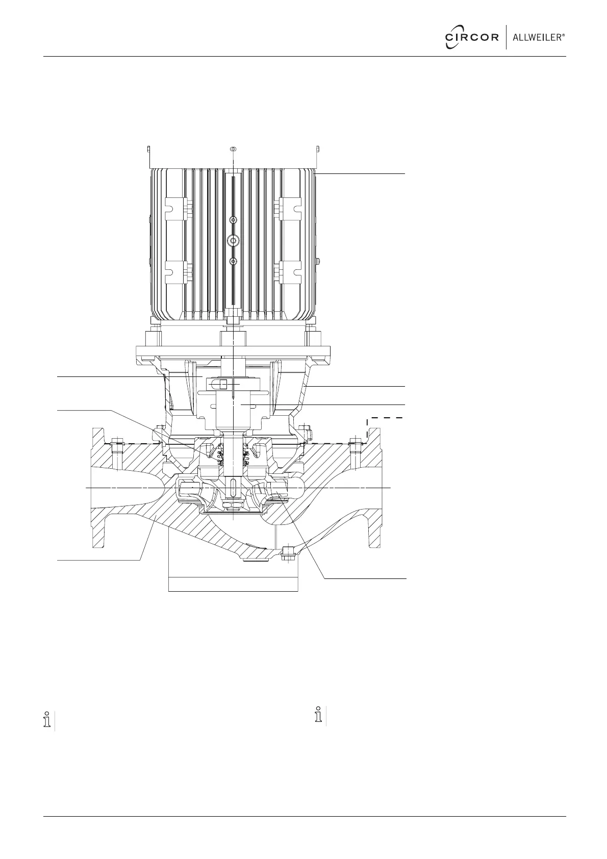
3.2 Layout
1
2
3
6
7
8
4
5
Fig. 5 Layout
1 Motor with fixed bearing at drive end
2 Motor bell housing
3 Stub shaft
4 Limit for heat insulation
5Impeller
6 Volute casing
7 Shaft seal
8 Guard sheet
3.3 Shaft seals
Only one of the following shaft seals can be used.
3.3.1 Mechanical seals
Mechanica
l seals have functional leaks.
• Single mechanical seal
• Single mechanical seal with quenching
12 NI series BA-2021.06 en-US 550 113 – 146-900/E
 Loading...