Installing the Electrolytic Cell and Flow Switch
The Cell and Flow Switch are to be fitted into the return line as the last pieces of equipment the water passes
through before returning to the pool: always after the pump, filter, heater (if applicable), etc. If a heater is present,
all equipment must be a minimum distance away, per heater manufacturer recommendations.
Refer to the overview diagram on page 14 for alternate configurations. For combined pool and spa systems with a
spillover, configurations #2 or #3 allow chlorination for both the pool and spa during spillover but preventing
possible over-chlorination when operating the spa only. Vertical Installation Kits are also available to minimize
plumbing space required and increase ease of installation (sold separately, available at www.circupool.com).
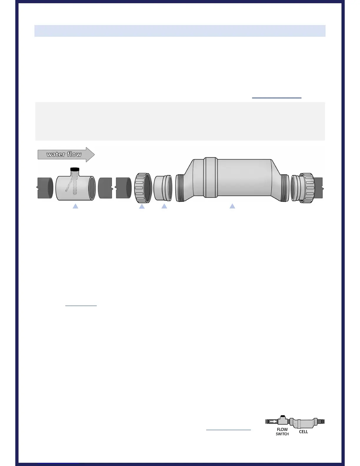
1. Lay out your equipment to ensure there is enough pipe space available; the Cell with unions is 15 ¾” in length,
and the Flow Switch is 4” in length.
2. On the pipe where the Cell will be installed, mark two lines 13 ¾” apart and then cut the pipe (for 2” plumbing).
3. Unscrew and removed Threaded Collars from Cell. Slide these over the pipe on each side of the cut, then glue
each Union to the cut pipe. Ensure O-Rings are in place on Unions.
- TIP: Glue one Union first, then when gluing second Union use Cell body to gauge the final distance need
between each Union; make small adjustments to second union’s slip connection while glue is still wet.
4. Only after the glue has fully cured, place the Cell into the opening between Unions and tighten the Threaded
Collars (by hand only) to ensure that the Cell fits securely in place. DO NOT OVER-TIGHTEN.
- When positioning the Cell, you can consider the side of the cell with the cord the "inlet" side. If installed
horizontally, ensure that the wire-side faces upwards.
5. Install the Flow Switch next to the Cell. Ensure that any excess glue does not become contact with movable switch.
- IMPORTANT: When positioning the Flow Switch, there must be at least 6 to 12” (30cm) of straight pipe before
the Flow Switch. If installed after the Electrolytic Cell, the Cell can be counted as straight pipe.
- To ensure proper operation, verify that the arrow on the flow switch (located on the black plastic) points in
the direction of water flow; the water flow must depress the hinged activator inside of the Flow Switch.
- If installed horizontally, ensure that the black plastic wire portion faces upwards. This portion is threaded and can
be turned during service to align arrow with water flow; additional thread seal tape may be added if necessary.
- When plumbing, the Flow Switch’s internal dimensions will add at least 1 ¼" if pipe is fully inserted into its slip
connections.
NOTE: When using a Variable-Speed or Multi-Speed pump on a low speed setting, or for
general circumstances where flow is less-than-adequate, the cell must be inverted in
order to ensure adequate flow & efficient chlorine production.