The CircuPool Universal Series is an advanced saltwater chlorination system designed for swimming pool sanitation. It utilizes electrolysis to continuously generate free chlorine from a low level of salt in the pool water, effectively killing bacteria and algae to maintain a clean and sparkling pool. The system is available in models UL25, UL40, and UL55, catering to various pool sizes and needs.
Function Description
The Universal Series operates as a chlorine generator, providing a steady supply of chlorine without the need for manual addition of chlorine. The core principle involves applying a small electric charge across a set of titanium plates within the Electrolytic Cell. This process produces Sodium Hypochlorite (NaOCl), which then dissociates into sodium (Na+) and hypochlorite (OCl-) ions. The hypochlorite ions combine with hydrogen (H+) ions from the water to form hypochlorous acid (HOCl), the active agent that destroys bacteria and algae and oxidizes organic matter. This form of chlorine acts quickly in the pipe, leaving a mild residual in the pool. Additionally, the Electrolytic Cell continuously "shocks" the incoming water, burning off oils, organic matter, and other particles that need to be oxidized. The system recycles salt, meaning the original salt molecules reform after cleaning the pool, and the salt itself is not consumed.
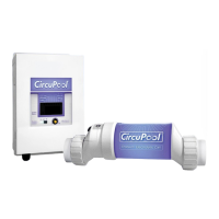
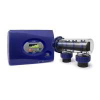
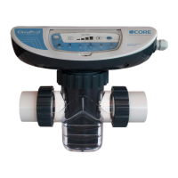
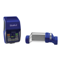
The system comprises three main components:
- Control Module: This wall-mounted unit supplies power to the Electrolytic Cell and allows users to customize the system's operation. It features an LCD display and LED indicator lights to provide system status and diagnostic information.
- Electrolytic Cell: This component contains bipolar titanium plates where chlorine is generated as water passes through. It is installed in the pool's return line.
- Flow Switch: This component ensures that there is adequate water flow (minimum 20 gpm) for the Cell to activate and generate chlorine safely.
Important Technical Specifications
- Salt Level: Ideal salt level for operation is approximately 3500 ppm (parts per million), with a suggested range of 3000-4000 ppm. The system requires about 30 lbs of salt for every 1000 gallons of water (or 3.6 kg for every 1000 liters).
- Water Flow Rate: A minimum water flow rate of 20 gpm is required for safe and effective operation of the electrolytic cell.
- Plumbing: The system is typically installed using 2" plumbing, but 1.5" plumbing can be accommodated with reducers. The Cell with unions is 15 ¼" in length, and the Flow Switch is 4" in length. A straight pipe section of at least 6 to 12" (30cm) is required before the Flow Switch.
- Electrical: The Control Module is shipped with a 240 VAC configuration but can be converted to 120 VAC by adjusting internal jumpers. It must be properly grounded and bonded. The unit can be wired to the pool pump's power source to turn on and off concurrently, or energized continuously for use with variable speed pumps, where the Flow Switch controls Cell power.
- Operating Temperature: The system will not produce chlorine at very cold temperatures, especially below 50°F (10°C), to extend the Cell's lifespan. Operation resumes when temperatures rise near 55°F (13°C).
- Salt Type: Only evaporated, granulated, non-iodized salt (Sodium Chloride) with at least 99% purity should be used. Avoid salts with anti-caking agents, Calcium Chloride, or Rock Salt.
Usage Features
- Chlorine Output Adjustment: The Control Module features a yellow dial to adjust chlorine output from 5% to 100%, allowing users to fine-tune chlorine production based on pool needs.
- Super Chlor Mode: A "Super Chlor" switch activates a temporary 100% chlorine output for 24 hours to address high bather loads, heavy rainfall, or cloudy water conditions.
- System Status Indicators:
- LED Indicator Lights:
- Power: Indicates the Control Module is receiving input power.
- Generate: Illuminates during normal chlorine generation. Flashing indicates water is too hot or cold for generation.
- Super Chlor: Illuminates when Super Chlor mode is active.
- Remote: Indicates control by a remote system.
- No Flow: Solidly illuminated when no flow is detected, stopping chlorine generation. Flashing indicates flow is restored, with a 60-second delay before generation resumes.
- Cell Maint.: Flashing is a reminder for proactive cell inspection; solid illumination means cell efficiency is greatly reduced and cleaning is required.
- Check Salt: Flashing indicates salt level is near minimum threshold; solid illumination means salt level is too low and cell is shut down.
- High Salt: Flashing indicates salt level is higher than necessary; solid illumination means salt level is too high and cell is shut down.
- LCD Display: Provides real-time information, cycled by the "SYSTEM STATUS" button:
- Average salt concentration (ppm).
- Pool Temperature (°F or °C).
- Cell Voltage (21.0 to 27.0 volts during generation).
- Cell Current (2.50 to 7.80 amps during generation).
- Selected Chlorine Output percentage level.
- Real-Time Salinity reading (xxxx PPM or x.x grams/Liter).
- System ID.
- Software revision level.
- Cell Version.
- Duty Cycle: The system employs an algorithm to determine when to actively generate chlorine, optimizing cell lifespan. During rest cycles, Cell Current and Real-Time Salinity readings may temporarily show zero.
- Variable Speed Pump Compatibility: The Control Module can be wired directly to the power source for continuous operation with variable speed pumps, allowing the Flow Switch to control cell activation.
- Power Protection: Features an external Fuse Reset button and an internal, replaceable ATO "blade-type" fuse for power protection.
Maintenance Features
- Cell Cleaning: The system notifies users via the "Cell Maint." LED when mineral scaling requires cleaning. The cleaning process involves removing the cell, mixing muriatic acid with water (1 part acid to 4 parts water), pouring the solution into the cell to cover components, allowing it to soak for up to 15 minutes, and then flushing it with water. Cleaning caps or stands are available for easier cleaning.
- Water Chemistry Balance: Regular monitoring and balancing of pool water chemistry (pH, Total Alkalinity, Calcium Hardness, Stabilizer/Cyanuric Acid, Saturation Index, Phosphates & Nitrates, Metals, TDS) are crucial for optimal system performance and longevity. Ideal levels are provided in the manual.
- Winterizing: The system automatically reduces chlorine production at low temperatures to extend cell life. In areas with freezing temperatures, the Electrolytic Cell must be drained to prevent damage. Winter bypass cells are available for continued water circulation without the electrolytic cell.
- Spring Start-up: Before powering on the chlorine generator after inactivity, pool water chemistry must be balanced and salt levels adjusted if water was drained.
- Cell Replacement: The Electrolytic Cell is designed for replacement at the end of its lifespan, with only genuine CircuPool replacement parts recommended to ensure quality and value.
- Troubleshooting Guide: The manual includes a comprehensive troubleshooting section to address common issues such as low chlorine residual, no power, and cell maintenance warnings, providing possible causes and suggested actions.
- Warranty: The product comes with a limited warranty, prorated over four years for residential use, covering defects in manufacture and materials. Commercial use has a one-year warranty. Exclusions include normal wear items (O-rings, fuses), improper pool chemistry, incorrect installation, negligence, unauthorized modifications, misuse, and environmental factors.